|
|
|
|
1.0. Project Background |
|


Oscilloscopes traditionally are hardware based using a CRT (Cathode Ray Tube) designed to display voltage variations (periodic or otherwise); they are bulky, expensive and have difficultly displaying low frequency waveforms.
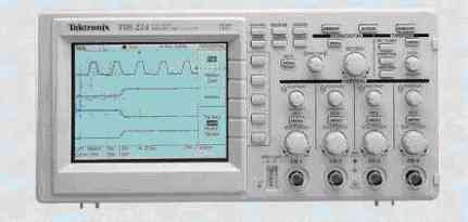
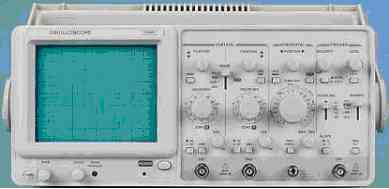 Figure 1.0a. 20MHz Analogue Dual Trace (CRT), about £400 [W2] |
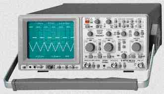 Figure 1.0b. 150MHz Analogue / Digital (CRT), about £1,600 [W1] |
“The word ‘Oscilloscope’ is an etymological hybrid. The first part derives from the Latin ‘oscillare’, to swing backwards and forwards; this in turn is from, ‘oscillum’, a little mask of Bacchus hung from the trees, especially in vineyards, and thus easily moved by the wind. The second part comes from the Classical Greek ‘skopein’, to observe, aim at, examine, from which developed the Latin ending ‘scopium’, which has been used to form names for instruments that enable the eye or ear to make observations.” [B1].
The heart of the traditionally CRT oscilloscope is the display screen itself, the CRT. “The CRT is a glass bulb which has had the air removed and then been sealed with a vacuum inside. At the front is a flat glass screen which is coated inside with a phosphor material. This phosphor will glow when struck by the fast moving electronics and produce light, emitted from the front and forming the spot and hence the trace. The rear of the CRT contains the electron ‘gun’ assembly. A small heater element is contained within a cylinder of metal called the cathode. When the heater is activated by applying a voltage across it, the cathode temperature rises and it then emits a stream of electrons.” [B2].
Figure 1.0c.
Diagram of a typical
Cathode-ray tube (CRT) construction.
This project attempts to achieve the same functionality as a traditional oscilloscope, using a PIC microcontroller for data acquisition (including appropriate analogue circuitry) which transfers the data to the PC (possibly via RS232, USB or Parallel). A Microsoft Windows based software application will then display the waveform as it would appear on a traditional CRT oscilloscope. This software application will have additional features not present on a traditional oscilloscope (e.g. printing / saving waveforms) with greater flexibly as additional features can be added as their developed without the need for new hardware.
The digital based oscilloscope should display very low frequency waveforms in real-time, but for higher frequency waveforms it is necessary to read a finite number of samples storing them into RAM. Once the memory is full (or the preset number of samples has been reached) the PIC will stop sampling and transfer the data to the PC, when ACK (acknowledgment) is received from the PC the PIC will start sampling again. This is known as a “Storage Oscilloscope”, but there are disadvantages e.g. it’s impossible to continuously monitor a waveform in real-time for more than the amount of samples that can be stored into the buffer as there would be gaps in the data.
Digital storage oscilloscopes have two main advantages over traditional analogue scopes: -
1. The ability to observe slow and very slow signals as a solid presentation on the screen. “Slow moving signals in the 10-100 Hz range are difficult to see and measure on a normal analogue oscilloscope due to the flicker of the trace and the short persistence of the spot on the screen. Very slow moving signals, less than 10 Hz, are impossible to view on an analogue scope. As fast as the spot traces out the waveform, the image fades and disappears before a complete picture can be formed.” [B2].
2. The ability to hold or retain a signal in memory for long periods.
The PIC microcontroller has a built-in ADC (8, 10 or 12 bits) which has a voltage range of 0 to 5V. This voltage range is not ideal as most oscilloscopes have a much wider voltage range including negative voltages (e.g. -100 to 100V); hence an analogue circuit is required to reduce the voltage positive signals so they fall between 2.5 and 5V and voltage negative signals between 0 and 2.5V (i.e. bipolar). The built-in ADC on the PIC is slow and will limit the maximum sampling frequency; hence an external Flash ADC with direct memory access will be required to produce a high-performance digital storage oscilloscope (e.g. AD9070 – 10Bit, 100MSPS ADC).
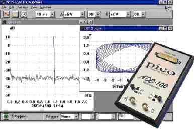
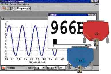
There are commercial digital scopes, but they are expensive and have small displays (unless they have video outputs or are based on PC displays).
|
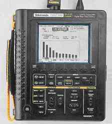 Figure 1.0e. 100MHz handheld digital storage oscilloscope, about £1,000. [W2] |
|
|
|