10.0. PIC Software Development

 
    10.1. Mark 1.c (Test RS232 Communications)
    10.2. Mark 2.c (Fully TestRS232 Communications)
    10.3. Mark 3.c (Real-time Mode: 1 channel, fixed sampling delay)
    10.4. Mark 4.c (Test RS232, Baud-Rate Set by dip-switches)
    10.5. Mark 5.c (Fully testSR232 communications, adjustable baud-rate)
    10.6. Mark 6.c (Real-time mode: 1 channel, fixed delay, adjustable baud-rate)
    10.7. Mark 7.c (Test Timer Interrupts)
    10.8. Mark 8.c. (Real-time mode: dual channel, fixed delay, adjustable baud-rate)
    10.9. Mark 9.c (Real-time mode: four channels, chop, interrupt time-base)
    10.10. Mark 10.c (Test External RAM Chip)
    10.11. Mark 11.c (Main Program)


The philosophy used during the development of the PIC code was to keep it simple, straightforward, comprehensible, and to a minimum. There are many small programs designed for testing the hardware and ideas, each program is labelled mark 1, 2, 3, etc… The end result is that the PIC code is gradually built up step-by-step, instead of writing the entire program at once. This ensures that operational results are obtained, as testing producers are carried out at each stage, while if the program was written all at once, there is little chance it will work and could prove difficult to debug.
 
The high-level programming language C was chosen and not the low-level assembly code normally associated with PIC programming. There are many advantages for using C including: ease of programming, ease of modification, reusability of code, use of standard functions (e.g. printf, getc, putc, etc…), etc… But there is one drawback, C code is much less efficient, for example typically code produced by the C compiler (CCS) is at least twice as large as that programmed in assembly. Since the PIC16F877 has a large program store (8k) and runs at 20MHz this drawback is not a problem.


10.1. Mark 1.c (Test RS232 Communications)
 
This program is extremely simple; basically it initialises RS232 communications and transmits “Testing…” once a second (see figure 10.1a). This program was used to test RS232 communications (transmit mode), including MAX232, PIC UART and cable. The PIC is connected to a PC which is running the DOS-based test program in RX terminal mode to receive the incoming characters.
 
Figure 10.1a. Mark 1 flowchart
 
Mark 1.c source code: -
/* --------------------------------------------------------
   | FILE    : mark 1.c                                   |
   | PROJECT : Low Cost PC Based Oscilloscope             |
   | DESC    : Test RS232                                 |
   | ==================================================== |
   | DATE    : 19/02/2002                                 |
   | BY      : Colin K McCord                             |
   | VERSION : 1.0                                        |
   -------------------------------------------------------- */
 
#include <16F877.h>
#device PIC16F877 *=16 ADC=10
 
#fuses HS,NOWDT,NOPROTECT,NOLVP
#use delay(clock = 4000000)   // 4MHz clock, change this value if using different clock speed.
#use rs232(baud=9600, xmit = PIN_C6, rcv = PIN_C7, parity = N, bits = 8)
 
main()
{
        while(TRUE)
        {      
               /* Note printf could be used but this function is wasteful and will not be used */
               putc('T');     // Transmit T
               putc('e');     // Transmit e
               putc('s');     // Transmit s
               putc('t');     // Transmit t
               putc('i');     // Transmit i
               putc('n');     // Transmit n
               putc('g');     // Transmit g
               putc('.');     // Transmit .
               putc('.');     // Transmit .
               putc('.');     // Transmit .
 
               delay_ms(1000);        // Preset delay, repeat every second
        }
}


10.2. Mark 2.c (Fully Test RS232 Communications)
 
This program is extremely simple; basically it initialises RS232 communications and waits for an incoming character, once a character is received the character is transmitted, this process repeats forever (see figure 10.2a). This program is used to fully test RS232 communications, using the test program in TX terminal mode to transmit a message and then in RX terminal mode to receive a message. A more comprehensive test can be carried out using the test program in the loop-back test mode; if this test passes it is certain that RS232 communications are optimal.   
 
Figure 10.2a. Mark 2 flowchart
 
Mark 2.c source code: -
/* -------------------------------------------------------
| FILE :    mark_2.c                                    |
| PROJECT : Low Cost PC Based Oscilloscope              |
| DESC :    Test Serial Communications, waits for an    |
|           incoming char and transmits the char.       |
| ====================================================  |
| DATE : 19/02/2002                                     |
| BY : Colin K McCord                                   |
| VERSION : 1.0                                         |
-------------------------------------------------------- */
        
 
#include <16F877.h>
#device PIC16F877 *=16 ADC=10
 
#fuses HS,NOWDT,NOPROTECT,NOLVP
#use delay(clock = 4000000)
#use rs232(baud=9600, xmit = PIN_C6, rcv = PIN_C7, parity = N, bits = 8)
 
main()
{
     /* Note kbhit() can be used to check for incoming char before calling getc() */
     while(TRUE)
     {
           putc(getc()); // Wait for incoming char and transmit....
     }
 
}


10.3. Mark 3.c (Real-Time Mode: 1 Channel, Fixed Sampling Delay)
 
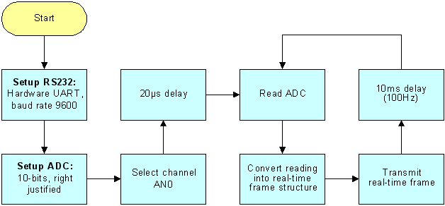
This program reads ADC channel AN0 and transmits the reading through RS232 using the real-time frame structure with a fixed sampling delay of 10mS (that’s a sample rate of 100Hz) before repeating (see figure 10.3a). This program is extremely useful, as it tests the ADC, the scope program, and the real-time frame structure. The sample rate is fixed; allow the sample delay can be manually modified (e.g. 1ms = 1000Hz) and the program recompiled and load into the PIC, hence testing of different sample rates is possible.
 
Figure 10.3a. Mark 3 flowchart
 
Mark 3.c source code: -
/* --------------------------------------------------------
   | FILE    : mark_3.c                                   |
   | PROJECT : Low Cost PC Based Oscilloscope             |
   | DESC    : Read CH1 ADC, transmit result through      |
   |         : RS232 using the real-time frame format.    |         
   | ==================================================== |
   | DATE    : 19/02/2002                                 |
   | BY      : Colin K McCord                             |
   | VERSION : 1.1                                        |
   -------------------------------------------------------- */
 
 
#include <16F877.h>
#device PIC16F877 *=16 ADC=10
 
// use #device adc = 10 to implement a 10-bit conversion,
// otherwise the default is 8-bits.
 
#fuses HS,NOWDT,NOPROTECT,NOLVP
#use delay(clock = 4000000)
#use rs232(baud=9600, xmit = PIN_C6, rcv = PIN_C7, parity = N, bits = 8)
 
 
main()
{
        // NOTE: by default in CCS all var's are unsigned
        long int adcValue;                    // 16-bit storage for ADC reading
        char adcHI,adcLO;                     // 8-bit storage for real-time frames.
 
        setup_adc_ports(A_ANALOG);            // RA0 - RA4 Analogue, RE0 - RE2 digital
        setup_adc(ADC_CLOCK_INTERNAL);        // Use internal ADC clock.
        set_adc_channel(0);
       
        delay_us(20);  // Delay for sampling cap to charge
 
        while(TRUE)
        {
               adcValue = read_adc(); // Get ADC reading
 
               /* Convert 16-bit adcValue to Real-time frame structure, CH1 */
               adcHI = (char)((adcValue >> 5)& 0x1f);       // 0|0|0|d9|d8|d7|d6|d5
               adcLO = (char)((adcValue & 0x1f)|0x80);      // 1|0|0|d4|d3|d2|d1|d0
                      
               putc(adcHI);   // Transmit Byte 1 (d9...d5)
               putc(adcLO);   // Transmit Byte 2 (d4...d0)
 
               delay_ms(10);  // Preset delay, repeat every 10ms
        }
}


10.4. Mark 4.c (Test RS232, Baud-Rate Set by Dip-Switches)
 
Same as mark 1.c with the addition of function SetBaudRate(), this function sets the UART baud-rate based on the positions of the DIP switches that are connected to port E. This program is used to test the reading of the DIP switches and RS232 communications at different baud rates. Note that the PIC must be running at 20MHz because the percentage error for 115Kbps is too large at slower clock speeds.
 
Mark 4.c source code: -
/* --------------------------------------------------------
   | FILE    : mark_4.c                                   |
   | PROJECT : Low Cost PC Based Oscilloscope             |
   | DESC    : Test RS232, baud rate set by dip switches. |
   | ==================================================== |
   | DATE    : 01/03/2002                                 |
   | BY      : Colin K McCord                             |
   | VERSION : 1.0                                        |
   -------------------------------------------------------- */
 
#include <16F877.h>
#device PIC16F877 *=16 ADC=10
 
#fuses HS,NOWDT,NOPROTECT,NOLVP
 
#byte   PORTE = 0x09   // PortE lives in File 9
 
/* Note 20MHz clock must be used for 115,000 bps, the % error is to large at slower speeds */
#use delay(clock = 20000000)  // 20MHz clock, change this value if using different clock speed.
#use rs232(baud=9600, xmit = PIN_C6, rcv = PIN_C7, parity = N, bits = 8)
 
#use    fast_io(E)             // Fast access to PortE (don't fiddle with TRISE)
 
/* Forward declaration of functions */
void SetBaudRate();
 
 
main()
{
        set_tris_e(0x17);      // TRISE = 00010111; RE2,RE1 and RE0 TTL Inputs
 
        SetBaudRate();
 
        while(TRUE)
        {      
               /* Note printf could be used but this function is wasteful and will not be used */
               putc('T');     // Transmit T
               putc('e');     // Transmit e
               putc('s');     // Transmit s
               putc('t');     // Transmit t
               putc('i');     // Transmit i
               putc('n');     // Transmit n
               putc('g');     // Transmit g
               putc('.');     // Transmit .
               putc('.');     // Transmit .
               putc('.');     // Transmit .
 
               delay_ms(1000);        // Preset delay, repeat every second
        }
}
 
 
void SetBaudRate()
{
        switch(PORTE & 0x07)   // Read dip switches and setup baud rate
        {
               case 0: set_uart_speed(4800);   break;
               case 1: set_uart_speed(9600);   break;
               case 2: set_uart_speed(14400);  break;
               case 3: set_uart_speed(19200);  break;
               case 4: set_uart_speed(32768);  break;
               case 5: set_uart_speed(38400);  break;
               case 6: set_uart_speed(57600);  break;
               case 7: set_uart_speed(115200); break;
        }
}


10.5. Mark 5.c (Fully Test RS232 Communications, Adjustable Baud-Rate)
 
Same as mark2.c with the addition of function SetBaudRate(), this function sets the UART baud-rate based on the positions of the DIP switches that are connected to port E. This program is used to fully test RS232 communications at different baud rates.
 
Mark 5.c source code: -
/* -------------------------------------------------------
  | FILE    : mark_5.c                                   |
  | PROJECT : Low Cost PC Based Oscilloscope             |
  | DESC    : Test Serial Communications, waits for an   |
  |           incoming char and transmits the char. Baud |
  |           rate set by dip switches.                  |
  | ==================================================== |
  | DATE    : 01/03/2002                                 |
  | BY      : Colin K McCord                             |
  | VERSION : 1.0                                        |
  -------------------------------------------------------- */      
 
 
#include <16F877.h>
#device PIC16F877 *=16 ADC=10
 
#fuses HS,NOWDT,NOPROTECT,NOLVP
 
#byte   PORTE = 0x09   // PortE lives in File 9
 
 
/* Note 20MHz clock must be used for 115,000 bps, the % error is to large at slower speeds */
#use delay(clock = 20000000)  // 20MHz clock.
#use rs232(baud=9600, xmit = PIN_C6, rcv = PIN_C7, parity = N, bits = 8)
 
/* Forward declaration of functions */
void SetBaudRate();
 
main()
{
        set_tris_e(0x17);      // TRISE = 00010111; RE2,RE1 and RE0 TTL Inputs
        SetBaudRate();
 
        /* Note kbhit() can be used to check for incoming char before calling getc() */
        while(TRUE)
        {
               putc(getc());  // Wait for incoming char and transmit....
        }
 
}
 
 
void SetBaudRate()
{
        switch(PORTE & 0x07)   // Read dip switches and setup baud rate
        {
               case 0: set_uart_speed(4800);   break;
               case 1: set_uart_speed(9600);   break;
               case 2: set_uart_speed(14400);  break;
                case 3: set_uart_speed(19200);   break;
               case 4: set_uart_speed(32768);  break;
               case 5: set_uart_speed(38400);  break;
               case 6: set_uart_speed(57600);  break;
               case 7: set_uart_speed(115200); break;
        }
}


10.6. Mark 6.c (Real-Time Mode: 1 Channel, Fixed Delay, Adjustable Baud-Rate)
 
Same as mark3.c with the addition of function SetBaudRate(), this function sets the UART baud-rate based on the positions of the DIP switches that are connected to port E. This program is used to test the real-time communications protocol and scope program at different baud rates.
 
 
Mark 6.c source code: -
/* --------------------------------------------------------
   | FILE    : mark_6.c                                  |
   | PROJECT : Low Cost PC Based Oscilloscope             |
   | DESC    : Read CH1 ADC, transmit result through      |
   |         : RS232 using the real-time frame format.    |
   |         : Baud rate set by dip-switches.             |
   | ==================================================== |
   | DATE    : 01/03/2002                                 |
   | BY      : Colin K McCord                             |
   | VERSION : 1.2                                        |
   -------------------------------------------------------- */
 
#include <16F877.h>
#device PIC16F877 *=16 ADC=10
 
// use #device adc = 10 to implement a 10-bit conversion,
// otherwise the default is 8-bits.
 
#fuses HS,NOWDT,NOPROTECT,NOLVP
 
#byte   PORTE = 0x09   // PortE lives in File 9
 
/* Note 20MHz clock must be used for 115,000 bps, the % error is to large at slower speeds */
#use delay(clock = 20000000)
#use rs232(baud=9600, xmit = PIN_C6, rcv = PIN_C7, parity = N, bits = 8)
 
#use    fast_io(E)             // Fast access to PortE (don't fiddle with TRISE)
 
/* Forward declaration of functions */
void SetBaudRate();
 
main()
{
        // NOTE: by default in CCS all var's are unsigned
        long int adcValue;                    // 16-bit storage for ADC reading
        char adcHI,adcLO;                      // 8-bit storage for real-time frames.
        set_tris_e(0x17);                      // TRISE = 00010111; RE2,RE1 and RE0 TTL Inputs
        SetBaudRate();
 
        setup_adc_ports(A_ANALOG);            // RA0 - RA4 Analogue, RE0 - RE2 digital
        setup_adc(ADC_CLOCK_INTERNAL);        // Use internal ADC clock.
        set_adc_channel(0);
       
        delay_us(20);  // Delay for sampling cap to charge
 
        while(TRUE)
        {
               adcValue = read_adc(); // Get ADC reading
 
               /* Convert 16-bit adcValue to Real-time frame structure, CH1 */
               adcHI = (char)((adcValue >> 5)& 0x1f);       // 0|0|0|d9|d8|d7|d6|d5
               adcLO = (char)((adcValue & 0x1f)|0x80);      // 1|0|0|d4|d3|d2|d1|d0
                      
               putc(adcHI);   // Transmit Byte 1 (d9...d5)
               putc(adcLO);   // Transmit Byte 2 (d4...d0)
 
               delay_ms(1);   // Preset delay, repeat every 1ms, that’s 1000 Hz
                              // baud rate must be at least 20000bps, try 32768bps.
        }
}
 
void SetBaudRate()
{
        switch(PORTE & 0x07)   // Read dip switches and setup baud rate
        {
               case 0: set_uart_speed(4800);   break;
               case 1: set_uart_speed(9600);   break;
               case 2: set_uart_speed(14400);  break;
                case 3: set_uart_speed(19200); break;
               case 4: set_uart_speed(32768);  break;
               case 5: set_uart_speed(38400);  break;
               case 6: set_uart_speed(57600);  break;
               case 7: set_uart_speed(115200); break;
        }
}


10.7. Mark 7.c (Test Timer Interrupts)
 
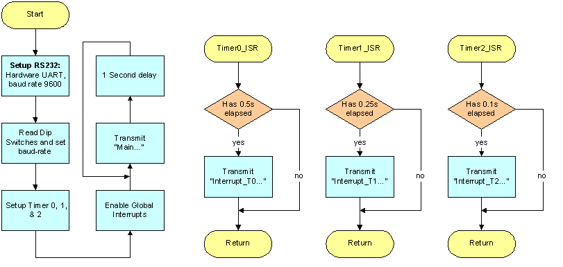
This program uses all of the PICs built-in timers, basically timers 0-2 are setup to cause an interrupt. An interrupt subroutine has been written for each timer; at preset intervals (0.5s, 0.25s, & 0.1s) a message is transmitted to the PC. The main program is stuck in a loop transmitting “main…” every second, Timer0_ISR transmits “Interrupt_T0…” every 0.5s, Timer1_ISR transmits “Interrupt_T1” every 0.25s and Timer2_ISR transmits “Interrupt_T2” 10-times a second. These messages are received using a PC running the DOS based test program in RX terminal mode, hence testing of the PIC timer interrupts including crude timing analysis is achieved, for example there should be two “Interrupt_T0…” messages between every “Main…”. See figure 10.7a for a simplified flowchart of the program.
 
 
Figure 10.7a.
Mark 7 flowchart
 
Mark 7.c source code: -
/* --------------------------------------------------------
   | FILE    : mark_7.c                                   |
   | PROJECT : Low Cost PC Based Oscilloscope             |
   | DESC    : Test timer interrupts                      |
   | ==================================================== |
   | DATE    : 05/03/2002                                 |
   | BY      : Colin K McCord                             |
   | VERSION : 1.1                                        |
   -------------------------------------------------------- */
 
#include <16F877.h>
#device PIC16F877 *=16 ADC=10
 
#fuses HS,NOWDT,NOPROTECT,NOLVP
 
#byte   PORTE = 0x09   // PortE lives in File 9
 
/* Note 20MHz clock must be used for 115,000 bps, the % error is to large at slower speeds */
#use delay(clock = 20000000)
#use rs232(baud=9600, xmit = PIN_C6, rcv = PIN_C7, parity = N, bits = 8)
 
#use    fast_io(E)             // Fast access to PortE (don't fiddle with TRISE)
 
#define T0_INTS_PER_SEC 76    // (20,000,000/(4*256*256))
#define T1_INTS_PER_SEC 76    // (20,000,000/(4*1*65536))
 
byte int_count0;              // Number of T0 interrupts left before a 0.5s has elapsed.
byte int_count1;              // Number of T1 interrupts left before a 0.25s has elapsed.
byte int_count2;              // Number of T2 interrupts left before a 100 msec has elapsed.
 
#int_rtcc                      // RTCC (timer0) interrupt, called every time RTCC overflows (255->0)
Timer0_ISR()          
{
        if(--int_count0==0)
        {
               printf("Interrupt_T0...");            // Every 0.5 seconds.
               int_count0 = T0_INTS_PER_SEC/2;
        }
}
 
#INT_TIMER1            // timer1 interrupt, called every time timer1 overflows (65536->0)
Timer1_ISR()          
{
        if(--int_count1==0)
        {
               printf("Interrupt_T1...");            // Every 0.25 seconds.
               int_count1 = T1_INTS_PER_SEC/4;
        }
}
 
#INT_TIMER2            // timer2 interrupt
Timer2_ISR()          
{
        if(--int_count2==0)
        {
               printf("Interrupt_T2...");            // Every 0.1 seconds.
               int_count2 = 100;
        }
}
 
/* Forward declaration of functions */
void SetBaudRate();
 
main()
{
        set_tris_e(0x17);      // TRISE = 00010111; RE2,RE1 and RE0 TTL Inputs
        SetBaudRate();
 
        /** Setup timer0 (RTCC) **/
        int_count0 = T0_INTS_PER_SEC/2;              // 0.5 seconds
        set_rtcc(0);
        setup_counters(RTCC_INTERNAL,RTCC_DIV_256);
        enable_interrupts(RTCC_ZERO);
 
        /** Setup timer1 **/
        int_count1 = T1_INTS_PER_SEC/4;              //0.25 second
        setup_timer_1(T1_DIV_BY_1 | T1_INTERNAL);   
        set_timer1(0);
        enable_interrupts(INT_TIMER1);
 
        /** Setup timer2 **/
        int_count2 = 100;                             // 0.1 second
        setup_timer_2 (T2_DIV_BY_4,125,9);            // interrupt every 1ms
        set_timer2(0);                              
        enable_interrupts(INT_TIMER2);
 
        enable_interrupts(GLOBAL);
 
        while(TRUE)
        {
               printf("Main...");
               delay_ms(1000);               // 1 second delay
        }
}
 
void SetBaudRate()
{
        switch(PORTE & 0x07)   // Read dip switches and setup baud rate
        {
               case 0: set_uart_speed(4800);   break;
               case 1: set_uart_speed(9600);   break;
               case 2: set_uart_speed(14400);  break;
               case 3: set_uart_speed(19200);   break;
               case 4: set_uart_speed(32768);  break;
               case 5: set_uart_speed(38400);  break;
               case 6: set_uart_speed(57600);  break;
               case 7: set_uart_speed(115200); break;
        }
}


10.8. Mark 8.c (Real-Time Mode: Dual Channel, Fixed Delay, Adjustable Baud-Rate)
 
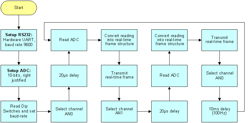
Same as mark6.c expect that instead of just sampling channel 1 the program chops between channel 1 and channel 2 (see figure 10.8a). This program is used to test the scope program in dual trace mode, triggering methods and stability of a trace when the other is being used as the trigger. Note the configuration of the ADC has been modified so that 32Tosc is used and not the internal RC oscillator. The reason for this change is that the PIC16F877 datasheet states “When the device frequencies are greater than 1MHz, the RC A/D conversion clock source is only recommended for sleep operation”.
 
 
Figure 10.8a.
Mark 8 flowchart
 
Mark 8.c source code: -
/* --------------------------------------------------------
   | FILE    : mark_8.c                                   |
   | PROJECT : Low Cost PC Based Oscilloscope             |
   | DESC    : Read CH1 & CH2, transmit result through    |
   |         : RS232 using the real-time frame format.    |
   |         : Baud rate set by dip-switches.             |
   | ==================================================== |
   | DATE    : 05/03/2002                                 |
   | BY      : Colin K McCord                             |
   | VERSION : 1.4                                        |
   -------------------------------------------------------- */
 
 
#include <16F877.h>
#device PIC16F877 *=16 ADC=10
 
// use #device adc = 10 to implement a 10-bit conversion,
// otherwise the default is 8-bits.
 
 
#fuses HS,NOWDT,NOPROTECT,NOLVP
 
#byte   PORTE = 0x09   // PortE lives in File 9
 
/* Note 20MHz clock must be used for 115,000 bps, the % error is to large at slower speeds */
#use delay(clock = 20000000)
#use rs232(baud=9600, xmit = PIN_C6, rcv = PIN_C7, parity = N, bits = 8)
 
#use    fast_io(E)             // Fast access to PortE (don't fiddle with TRISE)
 
/* Forward declaration of functions */
void SetBaudRate();
 
main()
{
        // NOTE: by default in CCS all var's are unsigned
        long int adcValue;            // 16-bit storage for ADC reading
        char adcHI,adcLO;             // 8-bit storage for real-time frames.
 
        set_tris_e(0x17);             // TRISE = 00010111; RE2,RE1 and RE0 TTL Inputs
        SetBaudRate();
 
        setup_adc_ports(A_ANALOG);    // RA0 - RA4 Analogue, RE0 - RE2 digital
        setup_adc(ADC_CLOCK_DIV_32); 
        set_adc_channel(0);
       
        delay_us(20);  // Delay for sampling cap to charge
 
        while(TRUE)
        {
               adcValue = read_adc(); // Get ADC reading
 
               /* Convert 16-bit adcValue to Real-time frame structure, CH1 */
               adcHI = (char)((adcValue >> 5)& 0x1f);       // 0|0|0|d9|d8|d7|d6|d5
               adcLO = (char)((adcValue & 0x1f)|0x80);      // 1|0|0|d4|d3|d2|d1|d0
                      
               putc(adcHI);   // Transmit Byte 1 (d9...d5)
               putc(adcLO);   // Transmit Byte 2 (d4...d0)
       
               set_adc_channel(1);
               delay_us(20);  // Delay for sampling cap to charge
 
               adcValue = read_adc(); // Get ADC reading
 
               /* Convert 16-bit adcValue to Real-time frame structure, CH2 */
               adcHI = (char)(((adcValue >> 5)& 0x1f)|0x20);        // 0|0|1|d9|d8|d7|d6|d5
               adcLO = (char)((adcValue & 0x1f)|0xA0);              // 1|0|1|d4|d3|d2|d1|d0
                      
               putc(adcHI);   // Transmit Byte 1 (d9...d5)
               putc(adcLO);   // Transmit Byte 2 (d4...d0)
 
 
               set_adc_channel(0);
               delay_ms(10);  // Preset delay, repeat every 10ms, that’s 100 Hz
        }
}
 
void SetBaudRate()
{
        switch(PORTE & 0x07)   // Read dip switches and setup baud rate
        {
               case 0: set_uart_speed(4800);   break;
               case 1: set_uart_speed(9600);   break;
               case 2: set_uart_speed(14400);  break;
               case 3: set_uart_speed(19200);  break;
               case 4: set_uart_speed(32768);  break;
               case 5: set_uart_speed(38400);  break;
               case 6: set_uart_speed(57600);  break;
               case 7: set_uart_speed(115200); break;
        }
}


10.9. Mark 9.c (Real-Time Mode: Four Channels, Chop, Interrupt Time-Base)
 
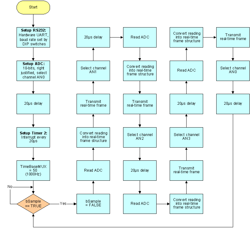
This program uses timer 2 (PIC built-in timer) as the time-base, the timer causes an interrupt every 20µS. The variable ‘TimeBaseMUX’ is the time-base multiplier (e.g. 100 Hz = 10ms, hence TimeBaseMUX = 500). Note no sampling is done during the interrupt routine as all interrupts are disabled while an interrupt is being processed, hence the interrupt routine needs to take less than 20µS to execute or timing would be inaccurate (e.g. say the interrupt routine execution time was longer than 20µS, during this time timer 2 cannot cause any more interrupts, hence accurate timing is lost). The main program loops continuously checking the ‘bSample’ flag, if the flag is true the function Sample_RealTime() is called, else it continues to loop. The ‘bSample’ flag is set in the time-base interrupt routine, keeping the interrupt routine short.
 
Interrupt driven time-base has one big advantage over using preset delays: delay routines do not take into consideration processing delays (e.g. waiting for UART buffer to empty), while the PICs real-time timer will continue to count no matter what the PIC is doing, and will cause an interrupt every 20µS (assuming interrupt routine is finished before it is time to called it again). 
 
This program samples all four channels (chop mode). For example channel 1 is sampled, then channel 2, then channel 3 and then channel 4. See figure 10.9a for a simplified flowchart of the program.


Figure 10.9a. Mark 9 flowchart
 
Mark 9.c source code: -
/* --------------------------------------------------------
   | FILE    : mark_9.c                                   |
   | PROJECT : Low Cost PC Based Oscilloscope             |
   | DESC    : real-time sampling using Interrupt         |
   |         : timebase, time-base is fixed. All channels |
   |         : are sampled CH1 to CH4 chop mode.          |
   |         : Baud rate set by dip-switches.             |
   | ==================================================== |
   | DATE    : 20/03/2002                                 |
   | BY      : Colin K McCord                             |
   | VERSION : 1.5                                        |
   -------------------------------------------------------- */
 
 
#include <16F877.h>
#device PIC16F877 *=16 ADC=10
 
// use #device adc = 10 to implement a 10-bit conversion,
// otherwise the default is 8-bits.
 
#fuses HS,NOWDT,NOPROTECT,NOLVP,NOBROWNOUT
 
#byte   PORTE = 0x09   // PortE lives in File 9
 
/* Note 20MHz clock must be used for 115,000 bps, the % error is to large at slower speeds */
#use delay(clock = 20000000)
#use rs232(baud=9600, xmit = PIN_C6, rcv = PIN_C7, parity = N, bits = 8)
 
#use    fast_io(E)             // Fast access to PortE (don't fiddle with TRISE)
 
long int TimeBase;
long int TimeBaseMUX;
char bSample;
 
/* Forward declaration of functions */
void SetBaudRate();
void Sample_RealTime();
 
 
/** TimeBase Interrupt called every 20uS that's 50KHz MAX **/
#INT_TIMER2
Timer2_ISR()
{
        // Sample Frequency = TimeBaseMUX * 20uS, e.g. 100Hz (1mS) = 20uS * 500
        if (--TimeBase==0)
        {
               TimeBase = TimeBaseMUX;      
               bSample = TRUE;
        }
 
}
 
 
main()
{
        bSample = FALSE;
 
        set_tris_e(0x17);             // TRISE = 00010111; RE2,RE1 and RE0 TTL Inputs
        SetBaudRate();
 
        setup_adc_ports(A_ANALOG);    // RA0 - RA4 Analog, RE0 - RE2 digital
        setup_adc(ADC_CLOCK_DIV_32); 
        set_adc_channel(0);
       
        delay_us(20);  // Delay for sampling cap to charge
                                     
        /** Setup Time-Base timer2 **/        // 1/(20,000,000/(4*1*100*1)) = 20uS
        setup_timer_2 (T2_DIV_BY_1,100,1);    // interrupt every 20us, that’s 50Khz max           
        set_timer2(0);                              
        enable_interrupts(INT_TIMER2);
 
        TimeBaseMUX = 50;             // 1000 Hz
        TimeBase = TimeBaseMUX;       // e.g. 50000 / 100 for 100 Hz (thats 500 * 20us = 10mS)
       
        enable_interrupts(GLOBAL);
 
        while(TRUE)
        {
               if(bSample == TRUE)
               {
                       bSample = FALSE;
                       Sample_RealTime();
               }
        }
}
void Sample_RealTime()
{
        // 20/03/2002. verision 1.0. sample ch1 to ch4, Chop Mode
 
        // NOTE: by default in CCS all var's are unsigned
        long int adcValue;            // 16-bit storage for ADC reading
        char adcHI,adcLO;             // 8-bit storage for real-time frames.
 
        /*** Channel 1 ***/
        adcValue = read_adc(); // Get ADC reading
 
        /* Convert 16-bit adcValue to Real-time frame structure, CH1 */
        adcHI = (char)((adcValue >> 5)& 0x1f);       // 0|0|0|d9|d8|d7|d6|d5
        adcLO = (char)((adcValue & 0x1f)|0x80);      // 1|0|0|d4|d3|d2|d1|d0
                      
        putc(adcHI);   // Transmit Byte 1 (d9...d5)
        putc(adcLO);   // Transmit Byte 2 (d4...d0)
       
 
        /*** Channel 2 ***/
        set_adc_channel(1);
        delay_us(20);  // Delay for sampling cap to charge
 
        adcValue = read_adc(); // Get ADC reading
 
        /* Convert 16-bit adcValue to Real-time frame structure, CH2 */
        adcHI = (char)(((adcValue >> 5)& 0x1f)|0x20);        // 0|0|1|d9|d8|d7|d6|d5
        adcLO = (char)((adcValue & 0x1f)|0xA0);              // 1|0|1|d4|d3|d2|d1|d0
                      
        putc(adcHI);   // Transmit Byte 1 (d9...d5)
        putc(adcLO);   // Transmit Byte 2 (d4...d0)
 
 
        /*** Channel 3 ***/
        set_adc_channel(2);
        delay_us(20);  // Delay for sampling cap to charge
 
        adcValue = read_adc(); // Get ADC reading
 
        /* Convert 16-bit adcValue to Real-time frame structure, CH3 */
        adcHI = (char)(((adcValue >> 5)& 0x1f)|0x40);        // 0|1|0|d9|d8|d7|d6|d5
        adcLO = (char)((adcValue & 0x1f)|0xC0);              // 1|1|0|d4|d3|d2|d1|d0
                      
        putc(adcHI);   // Transmit Byte 1 (d9...d5)
        putc(adcLO);   // Transmit Byte 2 (d4...d0)
 
 
        /*** Channel 4 ***/
        set_adc_channel(3);
        delay_us(20);  // Delay for sampling cap to charge
 
        adcValue = read_adc(); // Get ADC reading
 
        /* Convert 16-bit adcValue to Real-time frame structure, CH4 */
        adcHI = (char)(((adcValue >> 5)& 0x1f)|0x60);        // 0|1|1|d9|d8|d7|d6|d5
        adcLO = (char)((adcValue & 0x1f)|0xE0);              // 1|1|1|d4|d3|d2|d1|d0
                      
        putc(adcHI);   // Transmit Byte 1 (d9...d5)
        putc(adcLO);   // Transmit Byte 2 (d4...d0)
 
 
        /** Back to Channel 1 */
        set_adc_channel(0);
        delay_us(20);  // Delay for sampling cap to charge
 
}
 
 
void SetBaudRate()
{
        switch(PORTE & 0x07)   // Read dip switches and setup baud rate
        {
               case 0: set_uart_speed(4800);   break;
               case 1: set_uart_speed(9600);   break;
               case 2: set_uart_speed(14400);  break;
               case 3: set_uart_speed(19200);  break;
               case 4: set_uart_speed(32768);  break;
               case 5: set_uart_speed(38400);  break;
               case 6: set_uart_speed(57600);  break;
               case 7: set_uart_speed(115200); break;
        }
}


10.10. Mark 10.c (Test External RAM Chip)
 
This program carries out three tests: -
 
1.      Fill all memory locations with 0xFFh and check.
2.      Fill all memory locations with 0x00h and check.
3.      Fill all memory locations with the LSB of the address and check.
 
RS232 communication is used to relay the results to the PC; the DOS based program test.exe used in RX terminal mode is used to receive and display the results. This program is designed to test the functions used to access the RAM (ReadRAM, WriteRAM), and every location on the RAM chip.
 
Notice that there are 1 cycle delays in the ReadRAM and WriteRAM functions these delays make sure that the address and data lines are value before a read or write operation is completed. Note the RAM chip used has a reassembly fast access time; hence the RAM may operate correctly with these delays removed. This program is in preparation for storage mode operation.
 
/* --------------------------------------------------------
   | FILE    : mark_c10.c                                 |
   | PROJECT : Low Cost PC Based Oscilloscope             |
   | DESC    : Test RAM Chip                              |
   | ==================================================== |
   | DATE    : 21/03/2002                                 |
   | BY      : Colin K McCord                             |
   | VERSION : 1.2                                        |
   -------------------------------------------------------- */
 
#include <16F877.h>
#device PIC16F877 *=16 ADC=10
 
// use #device adc = 10 to implement a 10-bit conversion,
// otherwise the default is 8-bits.
 
#fuses HS,NOWDT,NOPROTECT,NOLVP,NOBROWNOUT
 
#byte   PORTB = 0x06   // PortB lives in File 6 (data bus)
#byte   PORTC = 0x07   // PortC lives in File 7 (address bus A12 to A8, RX, TX & R/W)
#byte   PORTD = 0x08   // PortD lives in File 8 (address bus A0 to A7)
#byte   PORTE = 0x09   // PortE lives in File 9 (used for DIP switches)
 
#bit    RW = PORTC.5   // RW = 0 for Write, and 1 for read
 
/* Note 20MHz clock must be used for 115,000 bps, the % error is to large at slower speeds */
#use delay(clock = 20000000)
#use rs232(baud=9600, xmit = PIN_C6, rcv = PIN_C7, parity = N, bits = 8)
 
#use    fast_io(B)     // Fast access to PortB (don't fiddle with TRISB)
#use    fast_io(C)     // Fast access to PortB (don't fiddle with TRISB)
#use    fast_io(D)     // Fast access to PortD (don't fiddle with TRISD)
#use    fast_io(E)     // Fast access to PortE (don't fiddle with TRISE)
 
/* Forward declaration of functions */
void SetBaudRate();
void WriteRAM(long int address, char data);
char ReadRAM(long int address);
 
main()
{      
        long int i;
        long int pass, fail;
        set_tris_c(0xC0);      // TRISD = 11000000; RC0 to RC5 TTL Outputs
                               // bits 7&6 must be set for UART to work    
        set_tris_d(0x00);      // TRISD = 00000000; RD0 to RD7 TTL Outputs
        port_b_pullups(FALSE); // Don't use internal pull up resistors
 
        SetBaudRate();
 
 
        while(TRUE)
        {
               delay_ms(5000); // 5 Sec delay
 
               printf("TEST RAM CHIP...");
 
 
               /** RAM Test 1 write 0xFF into all locations and check **/
               printf("\n\nTest 1 - Fill RAM with 0xFF --->");
               pass = 0;      // Reset Pass counter
               fail = 0;      // Reset Fail counter
 
               for (i=0;i<8192;i++)   // Write 0xFF to all locations
               {      
                       WriteRAM(i,0xFF);
               }
 
               for (i=0;i<8192;i++)
               {
                       if(ReadRAM(i) == 0xFF) pass++;
                       else fail++;
               }
              
               printf(" Passes = %lu, Fails = %lu", pass,fail);
 
 
               /** RAM Test 2 write 0x00 into all locations and check **/
               printf("\n\nTest 2 - Fill RAM with 0x00 --->");
               pass = 0;      // Reset Pass counter
               fail = 0;      // Reset Fail counter
 
               for (i=0;i<8192;i++)   // Write 0x00 to all locations
               {      
                       WriteRAM(i,0x00);
               }
 
               for (i=0;i<8192;i++)
               {
                       if(ReadRAM(i) == 0x00) pass++;
                       else fail++;
               }
              
               printf(" Passes = %lu, Fails = %lu", pass,fail);
 
 
               /** RAM Test 3 write LSB of address into all locations and check **/
               printf("\n\nTest 3 - Fill RAM with LSB of Address --->");
               pass = 0;      // Reset Pass counter
               fail = 0;      // Reset Fail counter
 
               for (i=0;i<8192;i++)   // Write LSB of address to all locations
               {      
                       WriteRAM(i,(char)i);
               }
 
               for (i=0;i<8192;i++)
               {
                       if(ReadRAM(i) == (char)i) pass++;
                       else fail++;
               }
              
               printf(" Passes = %lu, Fails = %lu", pass,fail);
 
 
               printf("\n\nEnd of RAMTEST, Hopefully work can now start on storage mode.\n\n");
 
        }      
 
sleep();
}


void SetBaudRate()
{
        // Verison 1.1, 22/3/2002, by CKM
 
        set_tris_e(0x17);      // TRISE = 00010111; RE2,RE1 and RE0 Inputs
                              // Parallel slave mode is ON, e.g. TTL Inputs, on Port E and D
 
        switch(PORTE & 0x07)   // Read dip switches and setup baud rate
        {
               case 0: set_uart_speed(4800);   break;
               case 1: set_uart_speed(9600);   break;
               case 2: set_uart_speed(14400);  break;
                case 3: set_uart_speed(19200);  break;
               case 4: set_uart_speed(32768);  break;
               case 5: set_uart_speed(38400);  break;
               case 6: set_uart_speed(57600);  break;
               case 7: set_uart_speed(115200); break;
        }
 
        set_tris_e(0x07);  // Turn OFF Parallel Slave Mode as this affects port D (Address Bus)
}
 
void WriteRAM(long int address, char data)
{
        // 20/03/2002, version 1.0 by Colin McCord
 
        set_tris_b(0x00);      // TRISE = 00000000; RB0 to RB7 TTL Outputs (data bus)
 
        RW = 1;                // Don't Write until address and data bus is setup.
 
        // Set Address
        PORTD = (char)address;                       // Set A7..A0
        PORTC = ((PORTC & 0xE0) | (address>>8));     // Set A12..A8
 
        PORTB = data;          // Put data on the data bus
 
       
        delay_cycles(1);       // 200nS delay, same as NOP, (1/20,000,000)*4*1) = 200nS
                              // make sure address & data is valid before write
 
        RW = 0;                // Write data to specified address
 
        delay_cycles(1);       // 200nS delay (same as NOP), make sure write is finished
        RW = 1;                // Back to Read Mode
}
 
char ReadRAM(long int address)
{
        // 20/03/2002, version 1.0 by Colin McCord
 
        set_tris_b(0xFF);      // TRISE = 11111111; RB0 to RB7 TTL Inputs
 
        RW = 1;                // Put RAM chip in Read Mode
 
        // Set Address
        PORTD = ((char)address);                     // Set A7..A0
        PORTC = ((PORTC & 0xE0) | (address>>8));     // Set A12..A8
 
        delay_cycles(1);       // 200nS delay, same as NOP, (1/20,000,000)*4*1) = 200nS
                              // make sure data is valid before reading
 
        return PORTB;
}


10.11. Mark 11.c (Main Program)


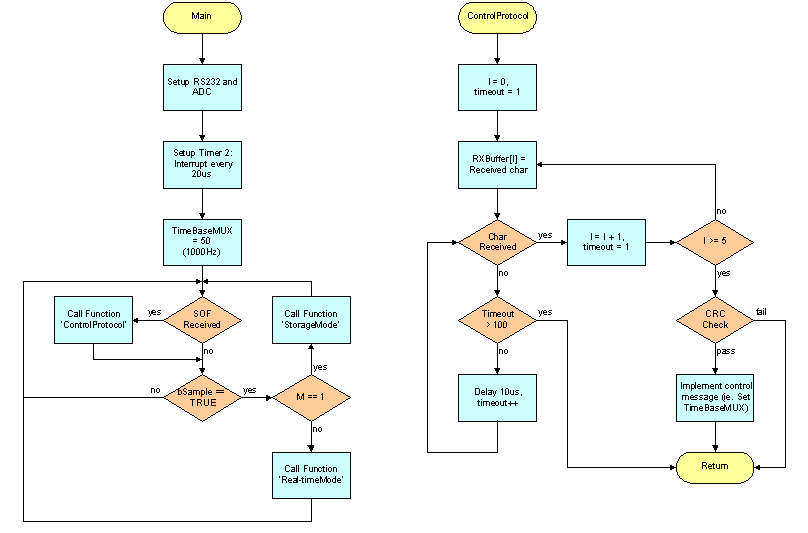
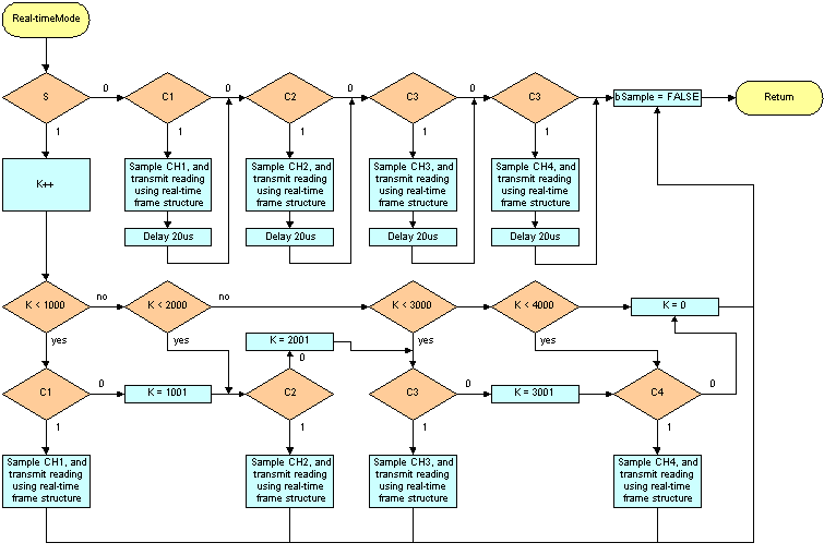
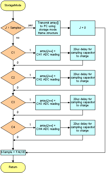
Note the Mark11.c program is not complete and the flowcharts above are draft flowcharts.


Final Year Project

Content Page

Colin's Home Page


This Web Page was last updated on Friday June 28, 2002
 

Home    About me    National Record Of Achievement    Hobbies / Interests   Guest Book    Contact Me    Links    Snooker   Amateur Radio    Site Map


© 2002 Designed by Colin K McCord

This website is best viewed by Microsoft Internet Explorer 6.0 at a resolution of 1024 x 768