|
|
|
|
6.0. Communication Protocol Development |
|
|
|
|
|
6.0. Communication Protocol Development |
|
6.1. Real-Time Mode
6.2. Storage
Mode
6.3. Control
Protocol
6.4. Frame
Structure: Real-Time Mode
6.5. Sample
Rate: Real-Time Mode
6.6. Frame
Structure: Storage Mode
6.7. Sample
Rate: Storage Mode
6.8. CRC16
(Cyclical Redundancy Check) used in Storage Mode
6.8.1. Comparison of Raw
Calculation CRC & Lookup Table CRC
6.9. Frame
Structure: Control Protocol
There are two main communication protocols: real-time and storage. Note there is an additional communication protocol required to control the PIC (e.g. change sample rate, change from real-time to storage, etc…). Because RS232 has separate transmit and receive lines, there is no chance of a collision with the real-time / storage data. Let’s call this additional communication protocol the ‘control’ protocol, note an interrupt (or PIC must check UART buffer regularly) must be setup in the PIC to let it know that there is a control message waiting to be read.
Reads one sample at a time sending each reading directly to the PC using RS232, note there is a delay (real-time clock) between readings which is specified by the PC using the ‘control’ protocol.
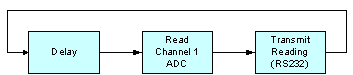
Figure 6.1a. Illustration of real-time mode with one channel
From figure 6.1b it is clear that timing is a big problem, as there are time delays for reading each analogue channel and transmitting the data. This problem is worse at high sample frequencies and one solution is to work around the problem and try to software offset the waveforms to compensate for these time delays. Another option is to use four PICs hence sampling can occur simultaneously, and use a master/slave communication protocol with some why of synchronising all the PICs. PIC microcontrollers are so cheap that this is a real option and was considered, multiple PICs in designs are widely used, unlike microprocessor design were it is usually expected that one microprocessor will control everything (e.g. PC, although there are lots of MPUs in a modern PC besides the Pentium).
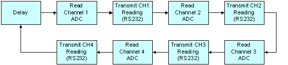
Figure 6.
1b. Illustration of real-time mode with four channels (chop mode)Figure 6.1c illustrates sampling four channels in the real-time mode using alternate sampling. Channel 1 is sampled 1000-times, then channel 2 is sampled 1000-times, then channel 3 is sampled 1000-times, then channel 4 is sampled 1000-times and the process repeats forever.
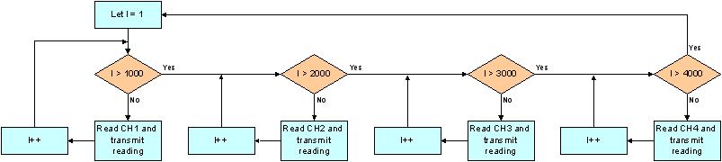
Figure 6.1c. Illustration of real-time mode with four channels (alternate mode)
The advantage of using alternate sampling is that all channels can be sampled at the maximum sample rate, while in chop mode each channel must share the RS232 throughput (RS232 bottleneck), for example say the maximum sample rate was 4KHz (set by the maximum RS232 frame structure throughput), one channel enabled would have a max sample rate of 4KHz, two channels enabled would have a max sample rate of 2KHz each, four channels enabled would have a max sample rate of 1KHz each.
But alternate has a disadvantage; timing information between different channels (e.g. channel 1 leads channel 2 by 25ms) is lost. It is possible to software correct this problem, for example using one of the PICs real-time timers it is known how mush time as elapsed between the sampling of channels, this information could be transmitted to the PC Scope program which then draws waveforms with the correct time gap between channels. Another disadvantage is that continuous monitoring is impossible as there are gaps in channel data (e.g. continuous monitoring required for an ECG signal). It is clear that alternate mode is only useful for periodical waveforms (e.g. sinewave), else chop mode should be used.
Read a finite number of samples, storing them into RAM (external RAM chip). The readings are then transferred to the PC in one large block, hence removing the RS232 bottleneck and providing faster sample rates.
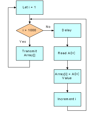
Figure 6.2a. Illustration of storage mode with one channel
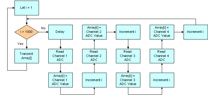
Figure 6.2b. Illustration of storage mode with four channels (chop mode)
Alternate sampling can applied to storage mode, but there is no real advantage over chop mode. Recall that the main reason of having alternate mode was to maximise the sample rate of each channel in the real-time mode. This no longer apples as storage mode removes the RS232 bottleneck, the new bottleneck is now the speed of the PICs ADC, hence alternate mode cannot increase channel sample rates.
The PIC checks the UART buffer regularly (or UART interrupt) checking to see if a control message is being received. Once a control message has been detected, the PIC leaves the main program and checks (CRC check) that the message is valid, if not return to the main program, if valid decode and implement the message. This process is illustrated in figure 6.3a.
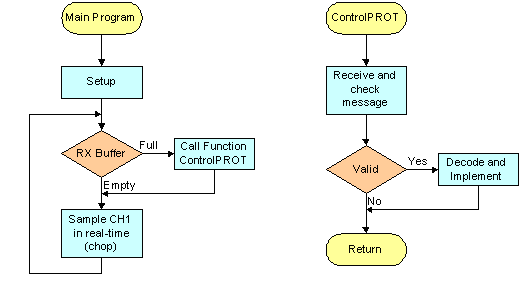
Figure 6.3a. Illustration of the control protocol
6.4. Frame Structure: Real-Time Mode
10-bit ADC, hence 2-bytes are sent per reading.
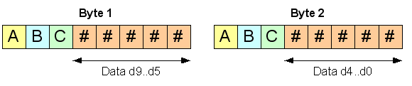
Figure 6.4a. Frame structure: Real Time.
If A = 0, byte 1 which contains data d9...d5 (Upper 5-bits of ADC reading).
If A = 1, byte 2 which contains data d4…d0 (Lower 5-bits of ADC reading).
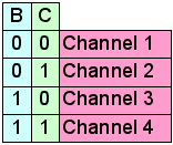
B & C specify what channel the data is for.
Since the RS232 communications is the bottleneck, it is important that the real-time communication protocol is as efficient as possible. At first it appears that the structure is 100% efficient as all bytes are used, and each one extremely important.
Yes this is partly true; however the only data of real value is the ADC readings, the reset are for identification purposes only. Hence the real efficiency of this frame structure is (10 data bits, 16 bits in total, hence efficiency = 10/16 x 100) 62.5%.
It is theoretically possible to use a frame structure that is 100% efficient, but this requires (because there is no identification code) extremely good synchronisation between the PC and the PIC. The main problem with this is that if a byte is lost (due to noise, bad line, buffer overflow, etc…) it would be extremely difficult to recover. The other option is to have the PC request each and every reading (Master/Slave), the problem with this is that there is a delay sending the request to the PIC and a processing delay hence this method would be much slower in reality.
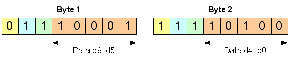
Figure 6.4b. Real-time frame structure example, channel 4 reads 564d (10,0011,0100b) from ADC
Notice there is no check sum or CRC, the reason for this is to maximise the data throughput. Clearly there is a problem; however the frame structure is designed in such a way that some errors can be detected. Note the cable between the MAX232 buffer (connect to PIC) and the PC will be high quality cable (short length) and errors should not occur that frequently anyway.
A few rules that must occur for the frame to be valid (non-valid frames are flushed): -
1. Byte 1 is always followed by byte 2 for a particular channel.
E.g. B1_CH1 ß B2_CH1 ß B1_CH3 ß B2_CH3 ß …. OK
E.g. B1_CH1 ß B1_CH3 ß B2_CH3 ß … Error (no B2_CH2) flush this byte
2. Channel readings can occur in any order as long as byte 2 follows byte 1.
E.g. B1_CH3 ß B2_CH3 ß B1_CH2 ß B2_CH2 ß …
If one or two readings are lost, it should not affect the appearance of the waveform too much, as there are at least 10 readings per cycle and probably at lot more at high sampling rates. Also because it is real-time the screen is continuously refreshed, hence the error will probably not stay on the screen for very long (a couple of milliseconds) until it is replaced by new readings.
6.5 Sample Rate: Real-Time Mode
The RS232 communications is the bottleneck as the maximum sampling frequency of PIC16F877 microcontroller ADC is higher than can be transmitted over RS232. Therefore it makes since to calculate the maximum sample rate based on how much data can be transmitted through RS232 at different baud rates.
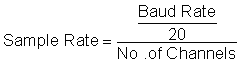
Two bytes are sent per frame, note each byte contains 8-bits plus a start and stop bit. Hence 20-bits are sent per reading.
|
Number of |
Max Sample Rate |
Max Sample rate |
Max Sample Rate at 33.6 Kbps |
|
1 |
5.75 KHz |
2.83 KHz |
1.68 KHz |
|
2 |
2.87 KHz |
1.41 KHz |
840 Hz |
|
3 |
1.91 KHz |
0.94 KHz |
560 Hz |
|
4 |
1.43 KHz |
0.70 KHz |
420 Hz |
Figure 6.5a. Table showing the theoretical real-time sample rates (chop, 10-bit ADC).
Note that the values shown in Figure 6.5a assume that there is no time delay between readings. Clearly this is not the case in practice and the actual maximum sample rates will be lower than specified e.g. PIC takes 19.72μS (see datasheet for PIC16F877) to acquire each sample, plus there will be processing delays. However these values should be reasonably accurate because the hardware UART is being used, hence the PIC can sample the next reading while the UART is transmitting the last reading.
Note if alternating sampling (not chop) is used the sample rate will not decrease with the number of channels, for example figure 6.5a states that the maximum sample rate for one channel at 115 kbps is 5.75 KHz, if alternate mode is used this maximum sampling rate still applies even if 4 channels are enabled. Recall that alternate mode is only useful for periodical waveforms.
The PIC16F877 has an 10-bit ADC, if speed is important the resolution could be reduced to 8-bits when sampling four channels. For example channels 1,2,3,4 are always transmitted along with sync frame (5-bytes for 4 channels, 80% efficient), hence the following sample rates are now possible: -
![]()
|
Number of |
Max Sample Rate |
Max Sample rate |
Max Sample Rate at 33.6 Kbps |
|
1 |
2.3 KHz |
1.132KHz |
672 Hz |
|
2 |
2.3 KHz |
1.132KHz |
672 Hz |
|
3 |
2.3 KHz |
1.132KHz |
672 Hz |
|
4 |
2.3 KHz |
1.132KHz |
672 Hz |
Figure 6.5b. Table showing the theoretical real-time sample rates (chop, 8-bit ADC).
Another possible method for increasing real-time sampling rates is to use two or more serial links. For example most PCs have two RS232 ports (more can be added by inserting serial cards), why not use both serial ports to receive the data. Obviously the PIC only has one hardware UART, hence the solution is to use the hardware UART plus a software UART (CSS C compiler automatically generates the code when non-hardware PINs are selected, which is reconfigurable throughout the program). Two bytes are sent (10-bit ADC) for each channel, hence put the first byte on COM1 and the second on COM2, this will double the maximum sampling rate. Note the MAX232CPE chip is a dual RS232 line driver chip hence no extra hardware is required, allow the additional software UART will push the PIC to the limits (should be OK at 20MHz).

|
Number of Channels |
Max Sample Rate at 230 Kbps (2 serial links at 115 Kbps) |
Max Sample rate at 115 Kbps (2 serial links at 56.6 Kbps) |
Max Sample Rate at 67.2 Kbps (2 serial links at 33.6 Kbps) |
|
1 |
11.5 KHz |
5.75 KHz |
3.36 KHz |
|
2 |
5.75 KHz |
2.87 KHz |
1.68 KHz |
|
3 |
3.83 KHz |
1.91 KHz |
1.12 KHz |
|
4 |
2.88 KHz |
1.43 KHz |
840 Hz |
Figure 6.5c. Table showing the theoretical real-time sample rates (chop, 10-bit ADC, dual RS232 cable).
For faster sample rates, storage mode must be used, for example the PIC samples a waveform at 20 KHz storing each reading into an array (e.g. external RAM chip). Then once a certain number of samples have been taken (say 200) the PIC stops sampling and sends the readings to the PC (via RS232) in one large block (including CRC or check sum), once ACK (Acknowledgement) is received from the PC the PIC starts sampling again and the process repeats forever. Another option is to use a different transport medium (e.g. USB / Parallel) which would allow for faster real-time sample rates.
Note the real-time communication protocol does not rely on the transport medium, hence if the transport medium is changed the real-time protocol should be OK. Expect for maybe USB as USB ports can be shared with other devices (many devices connected to the same port e.g. printer, scanner, mouse, etc…) hence the communication protocol must be compliant with the USB standard.
6.6. Frame Structure: Storage Mode
Figure 6.6a shows the frame structure for the storage mode, each field is 1 byte in size, expect for the ‘data’ field which is variable and its size is specified in the ‘count’ field.
Since each frame could contain up to 255 data bits (large block of data) it is much more likely that an error will error when compared to the short real-time frames. Hence the need for error detection, at present a 16-bit CRC is included in the frame which will detect almost every possible error (including burst errors).
|
Figure 6.6a. Frame Structure: Storage Mode |
But the generation of the CRC is processor hungry; at first it was thought that it may not be suitable with the PIC. Although it is possible to generate the CRC using a lookup table, this reduces processor load, but this lookup table uses a lot of RAM.
The plan is to use a 16-bit CRC for error detection, as this practically guarantees that all errors are detected. But if it turns out that it is impractical to implement on the PIC, a simple checksum will be used instead, but the disadvantage of this is that not all errors will be detected (burst errors will be a problem). Note all fields in the frame are included in the CRC (or maybe checksum) calculation e.g. SOF, COUNT, and DATA[i] … DATA[n].
The ‘data’ field uses the same frames as specified for the real-time frame structure. The big advantages of this is that the code reusable e.g. subroutines/functions can be written and used in the real-time and storage modes.
There are two options for checking if the frame is correct: -
1. Calculated the CRC for the received frame and compare with the received CRC.
2. Send the entire frame to the CRC function (including received CRC) and if the calculated CRC is zero then the frame is correct.
6.7. Sample Rate: Storage Mode
Since operating in storage mode, the maximum sampling rate is only limited by the maximum sampling rate of the PIC ADCs and not the RS232 link. The datasheet for the PIC16F877 specifies acquisition time (TACQ): -
TACQ = Amplifier Setting Time + Hold Capacitor Charging Time + Temperature Coefficient
= TAMP + TC + TCOFF
= 2μS + TC + [(Temperature – 25oC)(0.05μS/oC)]
TC = CHOLD (RIC + RSS + RS) ln(1/2047)
= -120pF(1kΩ + 7kΩ +10kΩ) ln(0.0004885)
= 16.47μS
TACQ = 2μS + 16.47μS + [(50oC – 25oC)(0.05μS/oC)]
= 19.72μS
Therefore theoretically the PICs ADC can sample at (1/19.72μS) 50.7 KHz. But according to the datasheet “after a conversion has completed, a 2.0 TAD delay must be complete before acquisition can begin again. During this time, the holding capacitor is not connected to the selected A/D input channel.” [D1]
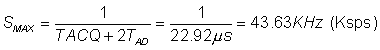
TAD is defined as the A/D conversion time per bit. For correct A/D conversions, the A/D conversion clock (TAD) must be selected to ensure a minimum TAD time of 1.6µs. Assuming a minimum A/D conversion clock (TAD) time of 1.6 µS (e.g. the PIC is running at 20 MHz with 32TOSC selected for TAD), the maximum sample rate is: -
For faster sample rates an external ADC with direct memory access is required.
6.8. CRC16 (Cyclical Redundancy Check) used in Storage Mode
Procedure: -
1. Load a 16-bit register with FFFF hex (all ‘1’s). Call this the CRC register.
2. Exclusive OR the first 8-bit bytes of the message with the low order byte of the 16-bit CRC register, putting the result in the CRC register.
3. Shift the CRC register one bit to the right, zero-filling the MSB. Extract and examine the LSB.
4.
If the LSB was 0: Do nothing –
proceed to step 5.
If the LSB was 1: EXOR the CRC register with the polynomial value 0xA001.
5. Repeat steps 3 and 4 until 8 shifts have been performed. When this is done, a complete 8-bit byte will have been processed.
6. Repeat steps 2 through 5 for the next 8-bit byte of the message. Continue doing this until all the bytes have been processed.
7. The final content of the CRC register is the CRC value.
8. Swap low & high bytes of CRC, Return CRC.
C code for producing CRC (pure calculation, no lookup table, PC Code): -
unsigned short CRC16(unsigned char *message, unsigned short data_length)
{
unsigned
short CRC = 0xFFFF, // CRC initialised with all '1's
i, // Loop Control
temp; // Temp for swap
while (data_length--) // Loop until all bytes calculated
{
CRC=CRC^(*message++);
for (i=0;i++<8;) // Shift all 8-bits
{
if (CRC & 0x0001) CRC = (CRC>>1) ^0xA001;
else CRC>>=1;
}
}
temp = CRC &
0xFF; // Temp storage for swap
CRC = ((CRC>>8)&0xFF) + (temp<<8); // Swap high and low byte
return (CRC); // Return calculated 16-bit CRC
}
C code for producing CRC (using lookup table): -
unsigned short CRC16(unsigned char *message, unsigned short data_length)
{
/* Table of CRC values for high-order byte */
static unsigned char Table_CRC_Hi[] = {
0X00, 0XC1, 0X81, 0X40, 0X01, 0XC0, 0X80, 0X41, 0X01, 0XC0, 0X80, 0X41, 0X00,
0XC1, 0X81,
0X40, 0X01, 0XC0, 0X80, 0X41, 0X00, 0XC1, 0X81, 0X40, 0X00, 0XC1, 0X81, 0X40,
0X01, 0XC0,
0X80, 0X41, 0X01, 0XC0, 0X80, 0X41, 0X00, 0XC1, 0X81, 0X40, 0X00, 0XC1, 0X81,
0X40, 0X01,
0XC0, 0X80, 0X41, 0X00, 0XC1, 0X81, 0X40, 0X01, 0XC0, 0X80, 0X41, 0X01, 0XC0,
0X80, 0X41,
0X00, 0XC1, 0X81, 0X40, 0X01, 0XC0, 0X80, 0X41, 0X00, 0XC1, 0X81, 0X40, 0X00,
0XC1, 0X81,
0X40, 0X01, 0XC0, 0X80, 0X41, 0X00, 0XC1, 0X81, 0X40, 0X01, 0XC0, 0X80, 0X41,
0X01, 0XC0,
0X80, 0X41, 0X00, 0XC1, 0X81, 0X40, 0X00, 0XC1, 0X81, 0X40, 0X01, 0XC0, 0X80,
0X41, 0X01,
0XC0, 0X80, 0X41, 0X00, 0XC1, 0X81, 0X40, 0X01, 0XC0, 0X80, 0X41, 0X00, 0XC1,
0X81, 0X40,
0X00, 0XC1, 0X81, 0X40, 0X01, 0XC0, 0X80, 0X41, 0X01, 0XC0, 0X80, 0X41, 0X00,
0XC1, 0X81,
0X40, 0X00, 0XC1, 0X81, 0X40, 0X01, 0XC0, 0X80, 0X41, 0X00, 0XC1, 0X81, 0X40,
0X01, 0XC0,
0X80, 0X41, 0X01, 0XC0, 0X80, 0X41, 0X00, 0XC1, 0X81, 0X40, 0X00, 0XC1, 0X81,
0X40, 0X01,
0XC0, 0X80, 0X41, 0X01, 0XC0, 0X80, 0X41, 0X00, 0XC1, 0X81, 0X40, 0X01, 0XC0,
0X80, 0X41,
0X00, 0XC1, 0X81, 0X40, 0X00, 0XC1, 0X81, 0X40, 0X01, 0XC0, 0X80, 0X41, 0X00,
0XC1, 0X81,
0X40, 0X01, 0XC0, 0X80, 0X41, 0X01, 0XC0, 0X80, 0X41, 0X00, 0XC1, 0X81, 0X40,
0X01, 0XC0,
0X80, 0X41, 0X00, 0XC1, 0X81, 0X40, 0X00, 0XC1, 0X81, 0X40, 0X01, 0XC0, 0X80,
0X41, 0X01,
0XC0, 0X80, 0X41, 0X00, 0XC1, 0X81, 0X40, 0X00, 0XC1, 0X81, 0X40, 0X01, 0XC0,
0X80, 0X41,
0X00, 0XC1, 0X81, 0X40, 0X01, 0XC0, 0X80, 0X41, 0X01, 0XC0, 0X80, 0X41, 0X00,
0XC1, 0X81,
0X40};
/* Table of CRC values for low-order byte */
static char Table_CRC_Lo[] = {
0X00, 0XC0, 0XC1, 0X01, 0XC3, 0X03, 0X02, 0XC2, 0XC6, 0X06, 0X07, 0XC7, 0X05,
0XC5, 0XC4,
0X04, 0XCC, 0X0C, 0X0D, 0XCD, 0X0F, 0XCF, 0XCE, 0X0E, 0X0A, 0XCA, 0XCB, 0X0B,
0XC9, 0X09,
0X08, 0XC8, 0XD8, 0X18, 0X19, 0XD9, 0X1B, 0XDB, 0XDA, 0X1A, 0X1E, 0XDE, 0XDF,
0X1F, 0XDD,
0X1D, 0X1C, 0XDC, 0X14, 0XD4, 0XD5, 0X15, 0XD7, 0X17, 0X16, 0XD6, 0XD2, 0X12,
0X13, 0XD3,
0X11, 0XD1, 0XD0, 0X10, 0XF0, 0X30, 0X31, 0XF1, 0X33, 0XF3, 0XF2, 0X32, 0X36,
0XF6, 0XF7,
0X37, 0XF5, 0X35, 0X34, 0XF4, 0X3C, 0XFC, 0XFD, 0X3D, 0XFF, 0X3F, 0X3E, 0XFE,
0XFA, 0X3A,
0X3B, 0XFB, 0X39, 0Xf9, 0XF8, 0X38, 0X28, 0XE8, 0XE9, 0X29, 0XEB, 0X2B, 0X2A,
0XEA, 0XEE,
0X2E, 0XEF, 0XEF, 0XED, 0XED, 0XEC, 0X2C, 0XE4, 0X24, 0X25, 0XE5, 0X27, 0XE7,
0XE6, 0X26,
0X22, 0XE2, 0XE3, 0X23, 0XE1, 0X21, 0X20, 0XE0, 0XA0, 0X60, 0X61, 0XA1, 0X63,
0XA3, 0XA2,
0X62, 0X66, 0XA6, 0XA7, 0X67, 0XA5, 0X65, 0X64, 0XA4, 0X6C, 0XAC, 0XAD, 0X6D,
0XAF, 0X6F,
0X6E, 0XAE, 0XAA, 0X6A, 0X6B, 0XAB, 0X69, 0XA9, 0XA8, 0X68, 0X78, 0XB8, 0XB9,
0X79, 0XBB,
0X7B, 0X7A, 0XBA, 0XBE, 0X7E, 0X7F, 0XBF, 0X7D, 0XBD, 0XBC, 0X7C, 0XB4, 0X74,
0X75, 0XB5,
0X77, 0XB7, 0XB6, 0X76, 0X72, 0XB2, 0XB3, 0X73, 0XB1, 0X71, 0X70, 0XB0, 0X50,
0X90, 0X91,
0X51, 0X93, 0X53, 0X52, 0X92, 0X96, 0X56, 0X57, 0X97, 0X55, 0X95, 0X94, 0X54,
0X9C, 0X5C,
0X5D, 0X9D, 0X5F, 0X9F, 0X9E, 0X5E, 0X5A, 0X9A, 0X9B, 0X5B, 0X99, 0X59, 0X58,
0X98, 0X88,
0X48, 0X49, 0X89, 0X4B, 0X8B, 0X8A, 0X4A, 0X4E, 0X8E, 0X8F, 0X4F, 0X8D, 0X4D,
0X4C, 0X8C,
0X44, 0X84, 0X85, 0X45, 0X87, 0X47, 0X46, 0X86, 0X82, 0X42, 0X43, 0X83, 0X41,
0X81, 0X80,
0X40};
unsigned char CRC_Hi = 0xFF; /* High byte of CRC initialised */
unsigned char CRC_Lo = 0xFF; /* Low byte of CRC initialised */
unsigned index=0; /* Will index into CRC lookup table */
while (data_length--)
{
index = CRC_Hi ^ *message++; /* Calculate the CRC */
CRC_Hi = CRC_Lo ^ Table_CRC_Hi[index];
CRC_Lo = Table_CRC_Lo [index];
}
return (CRC_Hi << 8 | CRC_Lo);
Example CRC calculation: -
|
Message Length: 1
Initialised CRC with all ‘1’s
|
6.8.1. Comparison of Raw Calculation CRC & Lookup Table CRC
Theoretically the raw calculation CRC function produces it result slower than the lookup table CRC function, but the lookup table will eat-up program memory (512 words). The objective of this simple experiment is to prove that this is the case and to find out exactly the performance of each, this information will be used to help decide, on which technique is best for this project. Simulations were carried out using Microchip MPLAB.
Raw calculation CRC test program (crc.c): -
#include <16F877.h>
long int CRC16(char *message, int length);
main()
{
long int
crcANS;
char test[5];
test[0] = 5;
test[1] = 4;
test[2] = 3;
test[3] = 2;
test[4] = 1;
crcANS = CRC16(test,5);
Sleep();
}
long int CRC16(char *message,int length)
{
/* 16-bit var's */
long int CRC
= 0xFFFF, /* CRC initialised with all '1's */
i, /* Loop Control */
temp; /* Temp for swap */
while (length--) /* Loop until all bytes calculated*/
{
CRC=CRC^(*message++);
for (i=0;i++<8;) /* Shift all 8-bits */
{
if (CRC & 0x0001) CRC = (CRC>>1) ^0xA001;
else CRC>>=1;
}
}
temp = CRC &
0xFF; /* Temp storage for swap */
CRC =
((CRC>>8)&0xFF) + (temp<<8); /* Swap high and low byte */
return (CRC); /* Return calculated 16-bit CRC */
}
Notice data types have been changed from that used in the PC version, e.g. char is 8-bit, short is 16-bit, int is 32-bit and long is 64-bit on a PC, while char is 8-bit, short is 1-bit, int is 8-bit, and long is 16-bit on a PIC.
Abstract from crc.lst: -
MPASM
CCS PCM C Compiler, Version 2.707, 8851
Filename: C:\WORK\COLIN\MPLAB\PROJECT\CRC\CRC.LST
ROM used: 116 (1%)
Largest free fragment is 2048
RAM used: 12 (7%) at main() level
22 (13%) worst case
Stack: 1 locations
...
...
Test array setup containing 5 elements, the test array is then send to the CRC function which then calculates the 16-bit CRC for the test array. Break point was inserted at the position of the Sleep () command, the stopwatch windows was opened and reset. Program was then simulated (stopwatch starts) until the break point is reached (stopwatch stops). Note the stopwatch time is the total time taken to execute all instructions in the test program and not just the CRC16 function. This is fine as the two test programs are identical except for the CRC16 function, therefore a good comparison can be made.
The screen dump of MPLAB after simulation (Raw Calculation): -
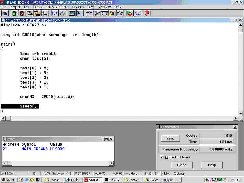
Figure 6.8.1a. Result of raw calculation CRC test
Total execution time for the raw calculation CRC test program was 1.64ms @4Mhz that’s 1638 Cycles.
Lookup table CRC test program (crcLT.c): -
#include <16F877.h>
/* Table of CRC values for high-order byte */
const char
Table_CRC_Hi[256] = {
0X00, 0XC1,
0X81, 0X40, 0X01, 0XC0, 0X80, 0X41, 0X01, 0XC0, 0X80, 0X41, 0X00, 0XC1, 0X81,
0X40, 0X01,
0XC0, 0X80, 0X41, 0X00, 0XC1, 0X81, 0X40, 0X00, 0XC1, 0X81, 0X40, 0X01, 0XC0,
0X80, 0X41,
0X01, 0XC0, 0X80, 0X41, 0X00, 0XC1, 0X81, 0X40, 0X00, 0XC1, 0X81, 0X40, 0X01,
0XC0, 0X80,
0X41, 0X00, 0XC1, 0X81, 0X40, 0X01, 0XC0, 0X80, 0X41, 0X01, 0XC0, 0X80, 0X41,
0X00, 0XC1,
0X81, 0X40, 0X01, 0XC0, 0X80, 0X41, 0X00, 0XC1, 0X81, 0X40, 0X00, 0XC1, 0X81,
0X40, 0X01,
0XC0, 0X80, 0X41, 0X00, 0XC1, 0X81, 0X40, 0X01, 0XC0, 0X80, 0X41, 0X01, 0XC0,
0X80, 0X41,
0X00, 0XC1, 0X81, 0X40, 0X00, 0XC1, 0X81, 0X40, 0X01, 0XC0, 0X80, 0X41, 0X01,
0XC0, 0X80,
0X41, 0X00, 0XC1, 0X81, 0X40, 0X01, 0XC0, 0X80, 0X41, 0X00, 0XC1, 0X81, 0X40,
0X00, 0XC1,
0X81, 0X40, 0X01, 0XC0, 0X80, 0X41, 0X01, 0XC0, 0X80, 0X41, 0X00, 0XC1, 0X81,
0X40, 0X00,
0XC1, 0X81, 0X40, 0X01, 0XC0, 0X80, 0X41, 0X00, 0XC1, 0X81, 0X40, 0X01, 0XC0,
0X80, 0X41,
0X01, 0XC0, 0X80, 0X41, 0X00, 0XC1, 0X81, 0X40, 0X00, 0XC1, 0X81, 0X40, 0X01,
0XC0, 0X80,
0X41, 0X01, 0XC0, 0X80, 0X41, 0X00, 0XC1, 0X81, 0X40, 0X01, 0XC0, 0X80, 0X41,
0X00, 0XC1,
0X81, 0X40, 0X00, 0XC1, 0X81, 0X40, 0X01, 0XC0, 0X80, 0X41, 0X00, 0XC1, 0X81,
0X40, 0X01,
0XC0, 0X80, 0X41, 0X01, 0XC0, 0X80, 0X41, 0X00, 0XC1, 0X81, 0X40, 0X01, 0XC0,
0X80, 0X41,
0X00, 0XC1, 0X81, 0X40, 0X00, 0XC1, 0X81, 0X40, 0X01, 0XC0, 0X80, 0X41, 0X01,
0XC0, 0X80,
0X41, 0X00, 0XC1, 0X81, 0X40, 0X00, 0XC1, 0X81, 0X40, 0X01, 0XC0, 0X80, 0X41,
0X00, 0XC1,
0X81, 0X40, 0X01, 0XC0, 0X80, 0X41, 0X01, 0XC0, 0X80, 0X41, 0X00, 0XC1, 0X81,
0X40 };
/* Table of CRC values for low-order byte */
const char Table_CRC_Lo[256] = {
0X00, 0XC0,
0XC1, 0X01, 0XC3, 0X03, 0X02, 0XC2, 0XC6, 0X06, 0X07, 0XC7, 0X05, 0XC5, 0XC4,
0X04, 0XCC,
0X0C, 0X0D, 0XCD, 0X0F, 0XCF, 0XCE, 0X0E, 0X0A, 0XCA, 0XCB, 0X0B, 0XC9, 0X09,
0X08, 0XC8,
0XD8, 0X18, 0X19, 0XD9, 0X1B, 0XDB, 0XDA, 0X1A, 0X1E, 0XDE, 0XDF, 0X1F, 0XDD,
0X1D, 0X1C,
0XDC, 0X14, 0XD4, 0XD5, 0X15, 0XD7, 0X17, 0X16, 0XD6, 0XD2, 0X12, 0X13, 0XD3,
0X11, 0XD1,
0XD0, 0X10, 0XF0, 0X30, 0X31, 0XF1, 0X33, 0XF3, 0XF2, 0X32, 0X36, 0XF6, 0XF7,
0X37, 0XF5,
0X35, 0X34, 0XF4, 0X3C, 0XFC, 0XFD, 0X3D, 0XFF, 0X3F, 0X3E, 0XFE, 0XFA, 0X3A,
0X3B, 0XFB,
0X39, 0Xf9, 0XF8, 0X38, 0X28, 0XE8, 0XE9, 0X29, 0XEB, 0X2B, 0X2A, 0XEA, 0XEE,
0X2E, 0XEF,
0XEF, 0XED, 0XED, 0XEC, 0X2C, 0XE4, 0X24, 0X25, 0XE5, 0X27, 0XE7, 0XE6, 0X26,
0X22, 0XE2,
0XE3, 0X23, 0XE1, 0X21, 0X20, 0XE0, 0XA0, 0X60, 0X61, 0XA1, 0X63, 0XA3, 0XA2,
0X62, 0X66,
0XA6, 0XA7, 0X67, 0XA5, 0X65, 0X64, 0XA4, 0X6C, 0XAC, 0XAD, 0X6D, 0XAF, 0X6F,
0X6E, 0XAE,
0XAA, 0X6A, 0X6B, 0XAB, 0X69, 0XA9, 0XA8, 0X68, 0X78, 0XB8, 0XB9, 0X79, 0XBB,
0X7B, 0X7A,
0XBA, 0XBE, 0X7E, 0X7F, 0XBF, 0X7D, 0XBD, 0XBC, 0X7C, 0XB4, 0X74, 0X75, 0XB5,
0X77, 0XB7,
0XB6, 0X76, 0X72, 0XB2, 0XB3, 0X73, 0XB1, 0X71, 0X70, 0XB0, 0X50, 0X90, 0X91,
0X51, 0X93,
0X53, 0X52, 0X92, 0X96, 0X56, 0X57, 0X97, 0X55, 0X95, 0X94, 0X54, 0X9C, 0X5C,
0X5D, 0X9D,
0X5F, 0X9F, 0X9E, 0X5E, 0X5A, 0X9A, 0X9B, 0X5B, 0X99, 0X59, 0X58, 0X98, 0X88,
0X48, 0X49,
0X89, 0X4B, 0X8B, 0X8A, 0X4A, 0X4E, 0X8E, 0X8F, 0X4F, 0X8D, 0X4D, 0X4C, 0X8C,
0X44, 0X84,
0X85, 0X45, 0X87, 0X47, 0X46, 0X86, 0X82, 0X42, 0X43, 0X83, 0X41, 0X81, 0X80,
0X40 };
long int CRC16(char *message, int length);
main()
{
long int crcANS;
char test[5];
test[0] = 5;
test[1] = 4;
test[2] = 3;
test[3] = 2;
test[4] = 1;
crcANS = CRC16(test,5);
Sleep();
}
long int CRC16(char *message,int length)
{
char CRC_Hi =
0xFF; /* High byte of CRC initialised */
char CRC_Lo =
0xFF; /* Low byte of CRC initialised */
long int CRC;
int index=0; /* Will index into CRC lookup table */
while (length--)
{
index
= CRC_Hi ^ *message++; /* Calculate the CRC */
CRC_Hi
= CRC_Lo ^ Table_CRC_Hi[index];
CRC_Lo
= Table_CRC_Lo [index];
}
CRC = CRC_Hi;
CRC =
(CRC<<8) | CRC_Lo;
return (CRC);
}
Abstract from crcLT.lst: -
MPASM
CCS PCM C Compiler, Version 2.707, 8851
Filename: C:\WORK\COLIN\MPLAB\PROJECT\CRC\CRCLT.LST
ROM used: 600 (7%)
Largest free fragment is 2048
RAM used: 12 (7%) at main() level
21 (12%) worst case
Stack: 2 locations
Figure 6.8.1b. Result of lookup table CRC test
Total execution time for the lookup table CRC test program was 286.00µS @4Mhz that’s 286 Cycles.
Clearly the lookup table CRC (286µs) runs over 5 times (5.7) faster than the raw calculation CRC (1.64ms) for this example. But unfortunately it is also clear that the lookup table CRC used 600 words of program memory (7% of total) and the raw calculation CRC only used 116 words (1% of total) hence the CRC lookup table uses 6 times more program memory than the raw calculation version. Obviously the reason for this is because the lookup table CRC uses 512 words of program memory for its lookup table.
Evidently if speed is important and there is plenty of program memory available, the lookup table CRC is the one to use. But if program memory is at a premium and speed is not important the raw calculation CRC is the one to use.
6.9. Frame Structure: Control Protocol
|
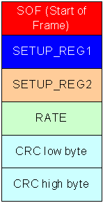
Figure 6.9a. Frame structure: control protocol |
Figure 6.9a shows the frame structure for the control protocol, each field is 1 byte in size. Since this control protocol is used to directly control the PIC, it is important that the PIC is able to check the frame before processing the information (e.g. the PIC should ignore random noise or corrupt frames). Hence a 16-bit CRC (same as used for storage mode) is used to make sure that the frame is valid before the PIC implements the control message.
The CRC takes some time to calculate hence there are crude checks that are carried out first before a CRC is calculated, as false control messages (random noise) would severely affect system performance. Hence the PIC waits for the SOF frame and ignores all other characters until a frame is detected, once a frame is detected it then waits for 5 more bytes. If these 5 bytes are not received within a certain time (e.g. max of 1.5ms gap between bytes) the PIC will timeout and return to what it was doing before the message was detected. If 5 bytes are received the frame is CRC check and if valid the message is decoded and implemented. Note it is possible that random noise could generate a SOF (e.g. 0x01) and 5 further bytes, but the CRC will make sure that the false frame is not implemented.
|
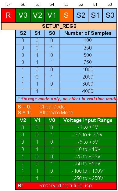
Figure 6.9c. SETUP_REG2 |
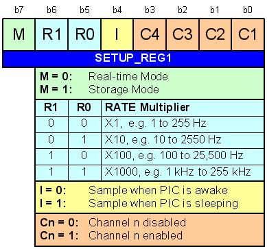
Figure 6.9b. SETUP_REG1
SETUP_REG1 is shown in figure 6.9b, this register specifies real-time/storage mode, sample rate multiplier, sample awake/sleeping and which channels are enabled / disabled. Note sampling when the PIC is sleeping is only an option for very slow sample rates as it takes a long time for the PIC to return to full speed after waking up. Recall that sampling when the PIC is sleeping results in more accurate ADC readings (less noise)
SETUP_REG2 is shown in figure 6.9c, this register specifies the number of samples to be stored into RAM (storage mode only), chop or alternate mode and the voltage input range (change gain of op-amps). Notice that b7 is marked as ‘R’, this means that the bit is not used and is reserved for future use.
Field RATE in figure 6.9a specifies the required sample rate, this figure is multiplied by the RATE multiplier that is specified in SETIP_REG1 (figure 6.9b). For example if RATE is 100 and RATE multiplier is 10 (R1 = 0, R0 = 1) the specified sample rate is 100 x 10 = 1000 Hz.
This Web Page was last updated on Friday June 28, 2002
Home About me National Record Of Achievement Hobbies / Interests Guest Book Contact Me Links Snooker Amateur Radio Site Map
|
© 2002 Designed by Colin K McCord |
|
This website is best viewed by Microsoft Internet Explorer 6.0 at a resolution of 1024 x 768