|
|
|
|
8.0. The Simulator Program |
|
|
|
|
|
8.0. The Simulator Program |
|
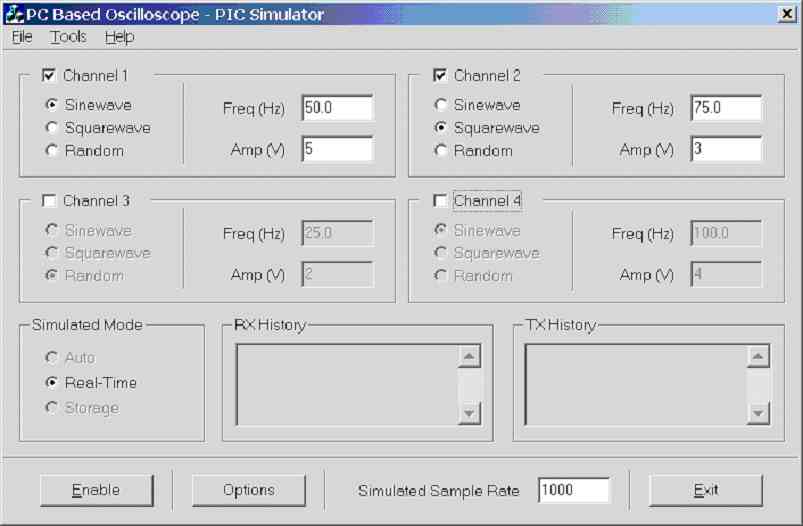 Figure 8.0a.
Screen dump of sim.exe V1.007a - 29/03/2002
If a
channel is disabled all of its controls are greyed (i.e. ch3 and ch4 are
disabled in figure 8.0a), notice that the user has the option to specify
real-time, storage or auto (controlled by PC). At present ‘auto’ and ‘storage’
mode have not been implemented. There are two large edit boxes that were
designed to be used to display RX and TX history in a low level format, for
debugging purposes, this feature was not implemented because there were no
communication problems during development.
The
program was used to test the communication protocols (real-time, storage,
control) and graphical scope display (including triggering methods) at
different baud rates. Note accurate timing is not simulated as this is
difficult to achieve, hence the best way of testing the timing is on an actual
PIC (hence the frequency settings for each channel are to be used as a guild
and are not accurate).
Note
the amplitude value of each channel is between 0 to 5V assuming this range is
selected on the scope program (e.g. input range). It was foreseen that the
scope program would control the input range, but this has not implement
(shortage of time, future development), hence for the amplitude values on the
simulator program to be accurate the correct range must be selected. This
program can still be used to test other voltage input ranges, for example the
simulator program 5V represents an ADC reading of 1024, and 0V represents an
ADC reading of 0, hence if -10 to 10 V range on the scope program is selected
5V will represent 10V, 2.5V will represent 0V and 0V will represent -10V.
Simulation of all four channels is possible, after the user has setup each
channel, communication with the scope program is enabled by clicking the
[Enable] button. The user can even specify a simulated sample rate, basically
specifying how many real-time frames are transmitted per second.
Figure
8.0b shows a screen dump of the ‘Options’ dialog box, which is used to
configure the RS232 serial port in a user-friendly manner.
Figure 8.0a.
Screen dump of sim.exe V1.007a - 29/03/2002
If a
channel is disabled all of its controls are greyed (i.e. ch3 and ch4 are
disabled in figure 8.0a), notice that the user has the option to specify
real-time, storage or auto (controlled by PC). At present ‘auto’ and ‘storage’
mode have not been implemented. There are two large edit boxes that were
designed to be used to display RX and TX history in a low level format, for
debugging purposes, this feature was not implemented because there were no
communication problems during development.
The
program was used to test the communication protocols (real-time, storage,
control) and graphical scope display (including triggering methods) at
different baud rates. Note accurate timing is not simulated as this is
difficult to achieve, hence the best way of testing the timing is on an actual
PIC (hence the frequency settings for each channel are to be used as a guild
and are not accurate).
Note
the amplitude value of each channel is between 0 to 5V assuming this range is
selected on the scope program (e.g. input range). It was foreseen that the
scope program would control the input range, but this has not implement
(shortage of time, future development), hence for the amplitude values on the
simulator program to be accurate the correct range must be selected. This
program can still be used to test other voltage input ranges, for example the
simulator program 5V represents an ADC reading of 1024, and 0V represents an
ADC reading of 0, hence if -10 to 10 V range on the scope program is selected
5V will represent 10V, 2.5V will represent 0V and 0V will represent -10V.
Simulation of all four channels is possible, after the user has setup each
channel, communication with the scope program is enabled by clicking the
[Enable] button. The user can even specify a simulated sample rate, basically
specifying how many real-time frames are transmitted per second.
Figure
8.0b shows a screen dump of the ‘Options’ dialog box, which is used to
configure the RS232 serial port in a user-friendly manner.
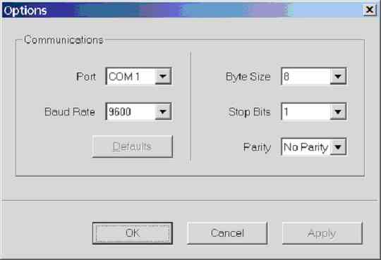 Figure 8.0b.
Screen dump of options dialog in sim.exe V1.007a – 29/03/2002
Figure
8.0c shows a screen dump of the ‘About’ dialog box, which displays information
about the program and the author, including some useful hyperlinks.
Figure 8.0b.
Screen dump of options dialog in sim.exe V1.007a – 29/03/2002
Figure
8.0c shows a screen dump of the ‘About’ dialog box, which displays information
about the program and the author, including some useful hyperlinks.
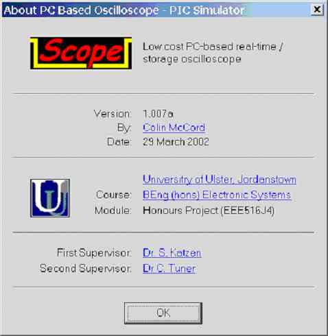 Figure 8.0c.
Screen dump of about dialog in sim.exe V1.007a – 29/03/2002
Figure 8.0c.
Screen dump of about dialog in sim.exe V1.007a – 29/03/2002
This Web Page was last updated on Friday June 28, 2002
Home About me National Record Of Achievement Hobbies / Interests Guest Book Contact Me Links Snooker Amateur Radio Site Map
|
© 2002 Designed by Colin K McCord |
|
This website is best viewed by Microsoft Internet Explorer 6.0 at a resolution of 1024 x 768