

Aerial & Signal Theory
|
|
|
|
Aerial & Signal Theory |
|
How does the signal get around the radio airwaves?
Common Radio Aerial and signal theory that exists
across the radio spectrum. The following information prevails for whether it's
CB radio, police radio, Television, broadcast radio, marine radio, airline
radio, mobile phones etc.
Radiation pattern
A signal radiates from an aerial in a certain pattern. Different aerials radiate signals in different patterns. For instance, a single standard vertical aerial will send out signals 360 degrees all around but not really up or down. A signal will hit the Atmosphere from the radiation angle, which is simply the angle at which the waves are traveling. From the top tip and bottom tip of an aerial is the least signal coming out, like the light from a flourescent bulb. When this same aerial is sitting horizontally, all though the pattern doesn't change that much the waves are now up and down, instead of all around. The tips of this aerial will again transmit the least.
Polarization
Polarization is whether radio waves are transmitted horizontally or vertically. A possible explanation for this is to say that the radio waves are on a different angle to the aerial. If you have a horizontal aerial, and a signal is coming from a vertical aerial the radio waves will clash with the aerial, and the aerial will not absorb the the waves at their full potential and thus conduct the signal down the co-axial cable to the radio. It's the same for horizontal signals being transmitted to vertical aerials.
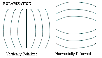 |
The diagram on the left represents an aerial standing vertically emitting radio waves. The diagram on the right represents an aerial sitting horizontally emitting radio waves. These radio waves don't just go out sideways, they go out of the aerial all around. Picture a donut, that is how radio waves come out of an aerial, in the shape of a donut (Depending on the aerial of course!). |
Co-Axial cable
Cable is your radio's lifeline through which the RF flows.
The signal from a CB transmitter goes through coaxial cable to an aerial. Maybe not just one aerial, perhaps 2 or 3 aerials. Not all at once of course, one aerial at a time. Perhaps aerials with different polarizations, radiation patterns (both explained above), and gain. At UHF the higher gain causes a flatter radiation angle resulting in more ground-plane aspect for your signal. This longer direct travel is achieved over flat terrain, and the range can be quite stunning in the country, however, a mobile in hilly areas would find themselves at a distinct disadvantage with a high-gain whip, especially where repeater access is needed.
There are 4 common cable specifications, each of 50ohm impedance (the resistance of the cable formed by some factors.), and their loss figures are rated on a 30m run.
The thinnest cable, and the one most suitable for mobile installations, is RG-58U or the superior RG-58C/U. RG-58 has a loss of 13.5dB over 30 meters at UHF CB frequencies, so even a 15m run there's a fair bit of loss. RG-213 is the most commonly used for base stations and represents an improvement of massive proportions over the RG-58 family. It has a loss factor of only 5dB over 30m, although after adding a few in-line connectors and other things, the figure will come to a good 6dB.
All of these cables are used in domestic/commercial environments. Radio stations however, that transmit kilowatts of power use co-axial cable that can be around 10cm thick.
Aerials have different names, such as Yagi-uda
Beam or just "Yagi" or "Beam", Dipole, longwire, Helical Whip or just Whip and
some others.
The Yagi-uda Beam.
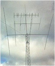 |
A multiple array of beams, including one that's even cross-polarized |
A Yagi-uda Beam is an aerial that looks
similar to a T.V aerial, only it's about 2 to 3 times larger (on HF & VHF
bands). The pieces that sit horizontally on the aerial are the elements and only
one of these actually wired to the co-axial cable. Imagine it like a car, a car
has 4 wheels but in Rear-wheel drive cars only the rear-wheels are powered, the
two front wheels are simply free-wheeling. On HF bands, each element is larger
than the other going from the front to back (front is shortest element) but
sometimes otherwise. The one element that gives out the signal is the driven
element and the ones in front are the director elements and the one behind is
the reflector element. The aerial radiates the signal horizontally in a certain
pattern. Radiation patterns are specified above. This aerial is one of
the aerials that are top selling, or most popularly constructed by advanced
Amateur operators because it has such gain over other aerials. It also directs
the signal in one direction, not just all around, making it stronger and also
increases the reception of other stations in the general direction of where the
aerial is pointed. The way to explain this is by saying that without a
directional aerial the signal goes around 360 degrees. The difference with the
Beam as stated before is that, it is directional, thus directing the signal in
one direction and enhancing receiving distance as well. It is partly called a
Beam because it beams the signal. These aerials cost between £150 and £1000.
Beams get smaller in smaller in size as the frequency becomes higher and higher.
Therefore at 477MHz UHF CB frequencies the beams can be as long as your arm and
as wide as you are! UHF beams tend to have more director and reflector elements
as it's so much smaller and easier to fit.
The Dipole.
The dipole is another Horizontal aerial and also emits waves horizontally and is therefore horizontally polarized. The Dipole is usually strung between two poles, masts or trees and is connected at the middle. At both ends there are insulators so that the signal doesn't escape into the earth. The coaxial cable is connected in a special manner. The center conductor, which is live, is connected to one half of the Dipole and the outer conductor, earth, is connected to the other half. The Dipole is an antenna in two pieces. Each half of the aerial is a certain length, a quarter wave length or half a wave length.
The center frequency at 27MHz is 11.11m long, dipoles are generally of quarter wavelength pieces, so the wavelength is 2.78m long and so each piece is 2.78m long. The wavelength of a frequency is calculated by an equation which is 300/frequency. So 300/27=11.11
The live part transmits the + (positive) part
of the signal and the earth, the - (negative) part of the signal. Like a wired
circuit they meet up in the air and create a closed circuit. Wavelengths
explained in detail, later on.
The Stationmaster or Itron for 27MHz CB.
 |
The Stationmaster is made up of Aluminum
making up the half wave of the CB band. It has a coil at the bottom that
mainly transmits the signal. The Itron however, has a sealed base containing
an automatic antenna tuner. The coil will weather. This type of aerial
stands vertically, being about 5.5 meters long or about 18ft (A half wave)
They transmit signals in vertical polarization, 360 degrees. |
'Co-linear' base station aerials for CB (or mobile).
|
Here, the choice is much simpler. Almost all 27MHz base antennae other than directional beams or "Yagi" arrays are of "co-linear" design. These vertical omni-directional antennae are usually manufactured from fiberglass and aluminum, and the main variant outside the construction and materials used is their gain figure. The most common figures are 6dB, 9dB and 12dB. Which one is right for you? It depends almost entirely on the surrounding terrain. The general rule is that the flatter the land around your station, the less the gain required. The gain figure alters the angle of radiation, this basically being whether your signal rises upwards or remains relatively flat. |
The longwire aerial.
The longwire is very similar to the Dipole in
appearance bit is different electrically. A longwire is connected at one end,
usually only the + is connected and the - runs straight to the ground in this
case. The - can also be connected to a water downpipe or metal stake in the
ground. Longwires are used for receivers, and are commonly used in the HF part
of the spectrum. (HF = High frequency, 3 - 30MHz)
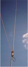
The Helical whip or just whip.

Helical Whips pictured
The Helical Whip is a name for an aerial for C.B, but also for Amateur and commercial two-way radio set-ups in cars. A Helical Whip is usually made up on a fiber glass rod, a wire is slowly wound up along the fibre glass rod. Near the top it winds into a coil and then smoothes out into an ordinary turn like before the coil. The coil part radiates the bulk of the signal. Due to wavelengths, the aerial might have to be tuned, and that is given the term "swer'ing" The "Swer" of an Aerial means, Standing Wave Ratio. S.W.R is its real name. It is the ratio of standing or reflected waves to roughly how many are getting out. It really measures the ratio of reflected waves, the less reflection the better, more reflection means trouble. If there is a ratio greater than 2:1, then components in the radio called `finals' can overheat and burnout. The finals are safety & power controllers so no part of the radio is damaged, the finals can be cheaply replaced (depending on make and brand).
The length of the antenna for 27MHz CB is extremely critical, the wavelength of 27MHz is 11m. For this reason many 27MHz "whips" come out of the factory pre-tuned. Quarter wave ground planes are the most basic whips. They are constructed of stainless steel or wire, for more flexibility. At 15cm length they are relativley small. Quarter-wave antennae have a naturally high angle of radiation (explained at top) and are best used in hilly country and with repeaters, as they are ideal for carrying the mobile signal from a low point such as your vehicle up to a repeater on the top of a mountain or city building.
The best mount position for a quarter wave is in the middle of any ground plane surface that can offer at least the radius of the whip and is unobstructed, such as the middle of the car's metal roof.
Centre-loaded helical whips are the next step up, with gain figures varying from 3dB to 4.5dB. This will give you a relatively good "flat" signal component for direct car-to-car or simplex range, as wall as a good angle for accessing repeaters.
Dipoles are the next step up, from a fairly middle-of-the-road 3dB to centre-loaded whips with a high gain figure of some 6dB.
You can also get mobile CB aerials for 27MHz up to a quarter wave length being 2.78m. This is not always practical to have on a car (the aerial can become damaged easily and can damage other objects as well), but produces the best signal radiation. They cost around £100.
Collin's Home Page Colin's Amateur Radio Page Colin's Snooker Page Colin's Guest Book Contact Me About Me
This Web page was last updated on Friday September 21, 2001
© 2001 Designed by Colin McCord